WOLFRAM SYSTEM MODELER
IntroductionIntroduction to the contents of the Rotating Machinery library |
|
Wolfram Language
In[1]:=
SystemModel["RotatingMachinery.Introduction"]
Out[1]:=
Information
With the Rotating Machinery library, you can model various types of machinery, such as motors, generators, pumps, fans and turbines. These pieces of machinery typically use a rotary motion to transfer energy from one place to another or perform other work. Rotating machinery is widely used in many industries, including manufacturing, power generation and transportation.
Figure 1: Steam and wind turbine (Source: [1, 2]).
The Rotating Machinery library is based on the MultiBody Library from the Modelica Standard Library (MSL). This means that the library is compatible with MSL and uses the same connectors used in the MultiBody Library. To create your first example, you can follow the steps in the Getting Started guide. This guide provides a step-by-step walk-through of the process, ending with a completed example.
Components
The Rotating Machinery Library contains components divided into five packages:
- Gears
- Masses
- Shafts
- Supports
- Rolling Bearings
All models have been developed according to [3, 4, 5].
Gears
The package is a collection of models for simulating and analyzing the behavior of gears. It includes models of inner and outer spur gears. The models are parametrized by the user, allowing them to specify the number of teeth, the pitch and other gear dimensions, as well as material properties.

Figure 2: Triple-gear transmission.
Masses
It is an extension of the masses that exist in the MultiBody Library with disks and balancing weights.
Balancing weights are small weights that are used to balance rotating objects, such as wheels, flywheels or other types of machinery. These weights are typically attached to the outside of the object to create imbalances in the object's mass distribution.
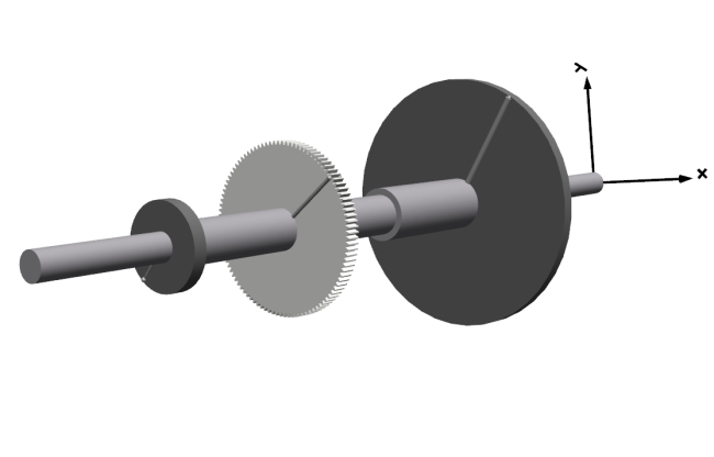 Figure 3: Disks with imbalances.
Shafts
Contains models of Euler–Bernoulli beams. The beams are modeled as a number of elements defined by the user. More elements will result in a beam model of higher fidelity, but at a cost of computation time.

Figure 4: Shaft with bearings on flexible supports.
The geometry of the circular beam can also be set by the user. The moment of inertia will then be calculated automatically. It is also possible to model beams put together in a loop structure.
Supports
Contains different models of supports such as pinned drive end, pinned non-drive end, flexible supports, housing, etc. These can, for example, be used to attach a shaft end in different ways or to put a rotating disk inside a housing with contact force.
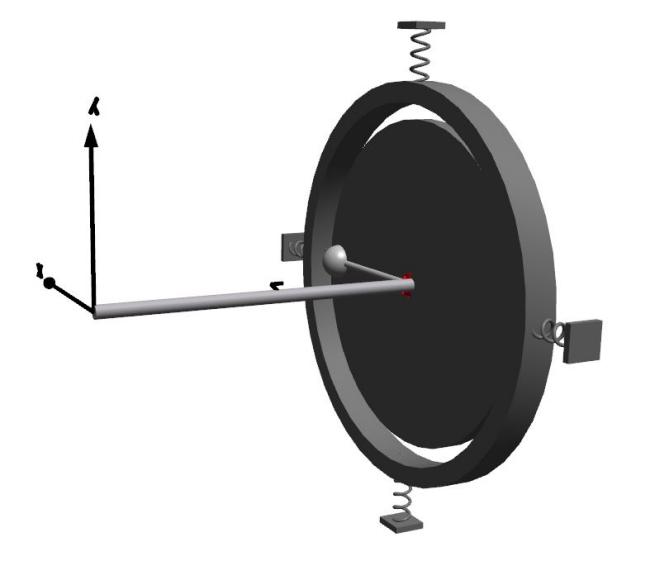
Figure 5: Housing ring.
Rolling Bearings
Contains cylindrical roller bearings from companies such as SKF, Timken, Koyo, FAG and NSK. Additionally, there is a generic roller bearing that can be parameterized by the user to model any cylindrical roller bearing available in the market. The available options to set are bearing dimensions and material properties.
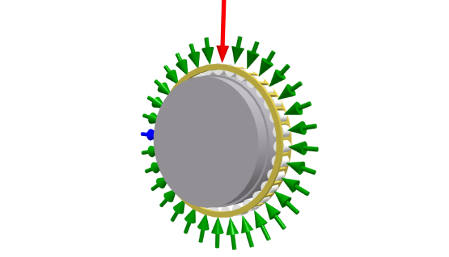
Figure 6: Roller bearing with animated roller forces.
It is also possible to simulate defects on the outer ring by incorporating an equivalent force amplitude. The forces between the rollers and rings (the blue one represents the one being examined, and the red arrow represents the location of the imposed defect) are calculated using Hertzian contact theory.
Examples
There are numerous examples included in this library to show how components can be used, or how systems might be assembled to investigate different phenomena listed below.
Contains examples related to bearings. Check this example, where you can analyze defect-related forces in the bearing.
Contains examples related to Campbell diagram analyses. See this example to investigate whirling frequencies at different speeds.
Contains examples related to gears. Build a two-wheeled gear train on shafts. >>
Contains examples related to basic rotor dynamics: damping. Check this example to determine shaft damping.
Contains an example related to balancing rotors >>
Contains examples related to contact models. Study contact forces between a disk and a housing. >>
Contains examples related to non-rotating flexible beams. See this example to inspect car axle vibrations.
References
[1] Wikipedia. "Steam Turbine." https://en.wikipedia.org/wiki/Steam_turbine.
[2] Wikipedia. "Wind Turbine." https://en.wikipedia.org/wiki/Wind_turbine.
[3] Ehrich, F. F . Handbook of Rotordynamics. McGraw-Hill, 1992.
[4] Ulbrich, H. "Rotordynamics Prediction in Engineering by Michel Lalanne, Guy Ferraris (Wiley, New York; ISBN 0471972886)." European Journal of Mechanics Solids 17, no. 6 (1998): 1039. https://doi.org/10.1016/S0997-7538(98)90510-1.
[5] Adams, M. L . Rotating Machinery Vibration: From Analysis to Troubleshooting (2nd ed.). CRC Press, 2010.