6.1 Cam ConstraintsA cam relationship is considered to be any relationship in which an arbitrarily defined space curve or surface is constrained to be in intimate contact with another point, curve, or surface. MechanicalSystems provides several special constraint functions that allow such arbitrary geometric elements to be used in the mechanism model. The definitive characteristic of cam constraints is that they force two surfaces to be simultaneously in contact with each other and, in most cases, tangent with each other at the point of contact. 6.1.1 2D Cam ConstraintsThe 2D cam constraints provided by Modeler2D cover four elementary cases of a cam and follower mechanism. In each case, the cam surface is defined by the locus of a single 2D point that is a function of one symbolic parameter. For example, the following 2D points are defined parametrically as functions of the symbol s. Each of these locuspointi would be valid as a Modeler2D cam profile. Here is a valid Modeler2D cam profile.
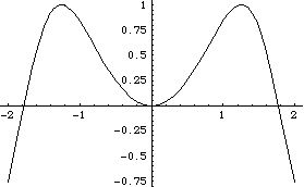
Out[2]= |  |
Here is another Modeler2D cam profile.
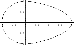
Out[4]= |  |
Note that although the Modeler2D cam constraints constrain one degree of freedom in the mechanism model, they actually add two (or three, as in CamToCam1) equations to the model. This is because each cam constraint also adds one (or two) symbols to the model's dependent variable list for a net loss of one degree of freedom. This anomaly is of no consequence to the user except when a cam constraint is used within TimeSwitch or StageSwitch. In these cases, the added symbol in the cam constraint must be dealt with in the other stages of the switch function, usually by using the Modeler2D Constraint function to set the added symbol equal to a constant. 2D cam constraints. The locus point that is passed to a Modeler2D cam constraint must be a valid Modeler2D point object containing the parametrically defined point. Also, the point must evaluate to a two-element list of differentiable expressions that are functionally dependent on the parameter alpha at the time the constraints are processed with SetConstraints. This is because the locus point is differentiated with respect to the parameter alpha by SetConstraints. Thus, if the locus point is not a function of alpha when passed to SetConstraints its derivative will be zero.
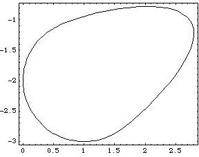
A special graphics function CamPlot is provided to parametrically plot the cam profiles in global coordinates. Note that CamPlot returns a Mathematica graphics object with the head Graphics, not a graphics primitive like most other Modeler2D graphics functions. A cam-specific graphics function. CamPlot produces the same output as would the built-in Mathematica ParametricPlot, except that CamPlot transforms the local cam profile into the global coordinate system. CamPlot does not evaluate directly to a Graphics object unless numeric values for the coordinate transformation are available. Instead, CamPlot evaluates to a SysPlot object that evaluates to a Graphics object when numbers are available for the transformation. This loads the Modeler2D package. CamPlot returns a SysPlot object.
Out[6]= |  |
When numbers are available for X2, Y2, and  2, the SysPlot object evaluates to a Graphics object. 2, the SysPlot object evaluates to a Graphics object. Here is the repositioned cam.
Out[7]= |  |
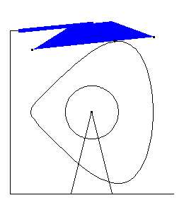
6.1.2 Example 2D Cam MechanismTo demonstrate the use of Modeler2D cam functions a 2D model of a rotating cam with a flat follower is developed. The model consists of two moving bodies, the cam and the follower. Here is the 2D cam-follower mechanism.
Cam ProfileThe cam profile used for this mechanism is defined in terms of trigonometric functions of the symbol alpha. The cam profile expression may contain user-defined parameters that are defined at runtime, but all of the functional dependence on the controlling parameter alpha must be present when the cam constraint is processed with SetConstraints. Thus, it is not possible to leave the cam profile defined as simply a two-element list of symbols, such as {xcam, ycam}, and then define xcam and ycam as functions of alpha at runtime. Here are two parametric expressions defining the locus of the cam profile. Here is a plot of the cam profile.
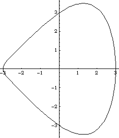
Out[12]= |  |
BodiesThree bodies are used for the cam-follower model. Names are defined for each of the body numbers in the model. Two points are required on the ground (body 1).
P1 is the rotational axis of the cam at {0, 0}.
P2 is the pivot axis of the follower at {- 3.5, 4.0}.Two points are required on the cam (body 2).
P1 is the rotational axis of the cam at local coordinate {0, 0}.
P2 is the locus point of the cam that was previously defined and named camprof.Three points are required on the follower (body 3).
P1 is the pivot axis of the follower at local coordinate {0, 0}.
P2 is the left end {0.5, - 1} of the flat surface that contacts the cam.
P3 is the right end {6.5, - 1} of the flat surface that contacts the cam.Here are all of the bodies in the cam-follower model.
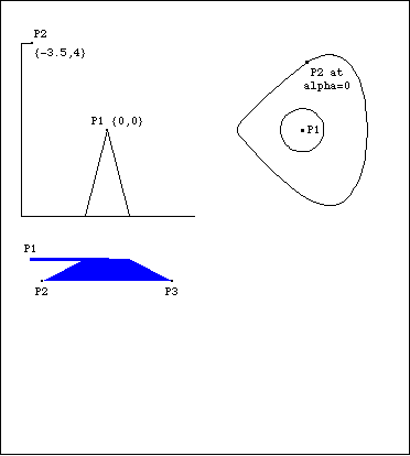
This is to set a nonzero initial guess for the rocker. ConstraintsThree regular constraints and one CamToLine1 constraint are required to model the cam-follower mechanism. A Revolute2 constraint forces the center of the cam to be coincident with its rotational axis on the ground.A Revolute2 constraint forces the pivot point of the follower to be coincident with its axis on the ground.A RotationLock1 constraint controls the angular coordinate of the cam. This driving constraint is used to specify the rotation of the cam as a function of T.A CamToLine1 constraint controls the single remaining degree of freedom. The point and line arguments are given in the same manner as would be used with any other constraint, except for the requirement that the local coordinates of the point be a function of the symbol alpha.Note that while CamToLine1 constrains one degree of freedom in the model, it actually adds two equations (one that forces the locus point to lie on the line and one that forces the line to be tangent to the cam at the point of contact) and one unknown alpha to the model. Here are the constraints for the cam-follower mechanism. RuntimeThe cam-follower mechanism model can now be run in the usual manner. Note the presence of the cam parameter alpha in the solution rule. At this value of alpha the cam locus point is placed at the point of contact between the cam and the follower. Now we run the model at T = 0.15.
Out[18]= |  |
Here is the cam-follower mechanism at T = 0.15.
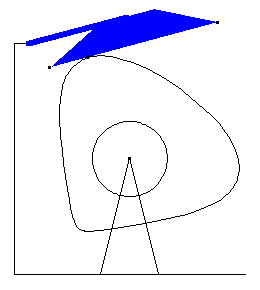
Now run the model at T = 0.30.
Out[19]= |  |
Here is the cam-follower mechanism at T = 0.30.
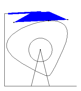
6.1.3 3D Cam ConstraintsThe 3D cam constraints provided by Modeler3D cover eight elementary cases of a cam and follower relationship. The 3D cam profiles used by Modeler3D fall into two basic categories: spatial surfaces and spatial curves. Spatial surfaces are defined by the locus of a single 3D point, the coordinates of which are a function of two independent parameters. Space curves are defined by a point that is a function of a single parameter.
In practice many 3D cam profiles are 2D in nature, in which case they are modeled using the techniques that were developed in Section 6.1.2 on 2D cams. Any 2D cam profile can be converted to a 3D space curve by inserting or appending a third constant coordinate to the 2D locus point.
Even when a true 3D surface profile is required, it can often be built up from the sum of two 2D curves that are functions of two different parameters. The following example uses one of the 2D cam profiles that was developed in Section 6.1.1 to generate a 3D cam surface. The only change to the 2D cam is the addition of the parameter t that directly specifies the local y coordinate of the cam. This example would serve as a valid cam profile for any Modeler3D cam constraint function. Here is a valid Modeler3D cam profile. Here is a plot of the cam profile.
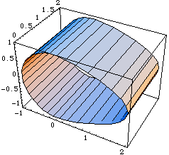
Out[21]= |  |
Note that although the Modeler3D cam constraints constrain one degree of freedom in the model (or two in the case of CurveToPoint2), they actually add between two and five equations to the model. This is because each cam constraint also adds one to four symbols to the model's dependent variable list (two parameters for each surface and one for each curve) for a net loss of one or two degrees of freedom. This anomaly is of no consequence to the user except when a cam constraint is used within TimeSwitch or StageSwitch. In these cases the added symbols in the cam constraint must be dealt with in the other stages of the switch function, usually by using the Modeler3D Constraint function to set the added symbols equal to a constant. Space curve constraints. Spatial surface constraints. Note that each symbol in a cam constraint must be accompanied by a numerical initial guess, guess.
The locus point that is passed to a Modeler3D cam constraint must be a valid Modeler3D point object containing the parametrically defined point. Also, the point must evaluate to a three-element list of differentiable expressions that are functionally dependent on the parameter alpha, at the time that the constraints are processed with SetConstraints. This is because the locus point is differentiated with respect to its controlling parameters by the SetConstraints function. Thus, if the locus point is not an explicit function of its parameters when passed to SetConstraints its derivative will be zero.
Note that all cam relationships are restricted to being in point contact. If two cam surfaces are defined such that they instantaneously have line contact instead of point contact, a singularity will result.
Some cam constraints are sensitive to which side of the cam surface the follower is on. The outside of a surface is defined as the side of the positive normal, which is the cross product of the direction of the surface gradient with respect to the first parameter and the direction of the surface gradient with respect to the second parameter.
CamPlot is a special graphics function provided to parametrically plot the cam profiles in global coordinates. Note that CamPlot returns a Mathematica graphics object, with the head Graphics, not a graphics primitive like most of the other Modeler3D graphics functions.

A cam-specific graphics function. CamPlot produces the same output as would ParametricPlot, except that CamPlot transforms the cam profile into the global coordinate system. CamPlot does not evaluate directly to a Graphics object because numeric values for the coordinate transformation are not available. Instead, CamPlot returns a SysPlot object that evaluates to a Graphics object when numbers are available for the transformation. This loads the Modeler3D package. CamPlot returns a SysPlot object.
Out[23]= |  |
When numbers are available for X2, Y2, and so on, the SysPlot object evaluates to a Graphics object. Here we show the repositioned cam surface.
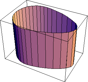
Out[24]= |  |
6.1.4 Example 3D Cam MechanismTo demonstrate the use of Modeler3D cam functions, a 3D model of a rotating cam with a spherical follower is developed. The model consists of two moving bodies, the cam and the follower. Here is the 3D cam-follower model.
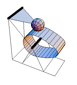
Cam ProfileThe cam profile used for this mechanism is defined in terms of trigonometric functions of the symbols alpha and beta. The cam profile expression may contain user-defined parameters that are defined at runtime, but all of the functional dependence on the controlling parameters, alpha and beta, must be present when the cam profile is processed with SetConstraints. Thus, it is not possible to leave the cam profile defined as simply a three element list of symbols, such as {xcam, ycam, zcam}, and then define xcam, ycam, and zcam as functions of alpha and beta at runtime.
The cam surface is the same as the one developed and plotted in Section 6.1.3. Here are the parametric expressions defining the locus of the cam surface. BodiesThree bodies are used for the cam-follower model. Names are defined for each of the body numbers in the model. Four points are required on the ground (body 1).
P1 and P2 are the two ends of the rotational axis of the cam at local coordinates {0, 0, 0} and {0, 2, 0}.
P3 and P4 are the two ends of the rotational axis of the follower at local coordinates {- 2, 0, 2} and {- 2, 2, 2}.Three points are required on the cam (body 2).
P1 and P2 are the two ends of the rotational axis of the cam at local coordinates {0, 0, 0} and {0, 2, 0}.
P3 is the locus point of the cam that was previously defined and named camsurf.Three points are required on the follower (body 3).
P1 and P2 are the two ends of the rotational axis of the follower at local coordinates {0, 0, 0} and {0, 2, 0}.
P3 is the center of the spherical cam follower at {2, 1, 0}.Here are all of the bodies in the cam model.
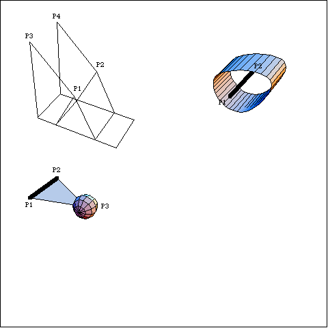
SetBodies is used here only to set a nonzero initial guess for the follower. ConstraintsThree regular constraints and one cam constraint are required to model the cam-follower mechanism. A Revolute5 constraint forces the axis of the cam to be coincident with its rotational axis on the ground.A Revolute5 constraint forces the pivot axis of the follower to be coincident with its axis on the ground.A ProjectedAngle1 constraint controls the angular coordinate of the cam. This driving constraint specifies the rotation of the cam as a function of T.A CamToSphere1 constraint controls the one remaining degree of freedom. The point arguments to CamToSphere1 are given in the same syntax as would be used with any other Modeler3D constraint, except for the requirement that the local coordinates of the locuspoint be a function of the symbols, alpha and beta.Note that while CamToSphere1 constrains one degree of freedom in the model, it actually adds three equations (one that forces the spherical follower to lie a specified distance away from the cam surface, and two more that force the cam surface to be tangent at the point of contact) and two unknowns, alpha and beta, to the model. Here are the constraints for the cam-follower mechanism. RuntimeThe cam-follower mechanism model can now be run in the usual manner. Note the presence of the cam parameters, alpha and beta, in the solution rule. At these values of alpha and beta the cam locus point is placed at the point of contact between the cam and the follower. Now the model is run at T = 0.10.
Out[31]= |  |
Here is the cam-follower mechanism at T = 0.1.
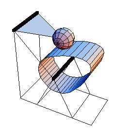
The model is run again at T = 0.20.
Out[32]= |  |
Here is the cam-follower at T = 0.20.
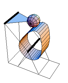
6.1.5 Splined CamsIn designing an arbitrary cam mechanism it is necessary to be able to describe an arbitrary cam surface, one that is not constrained to be a series of piecewise continuous functions each coded in by the user, such as the examples in Sections 6.1.2 and 6.1.4. One way to define such an arbitrary curve or surface is with Mathematica's InterpolatingFunction objects built with the Interpolation function. Thus, the required sequence of piecewise continuous functions is assembled by Mathematica, while the user merely inputs discrete data.
While a cam surface so defined may work in a Mech model, it may also create some numerical problems. One basic requirement for a valid Mech cam profile is that it have zeroth- and first-order continuity. The Interpolation function uses cubic interpolation to fit the polynomials to the supplied data. This results in a curve that has zeroth-order, not first-order, continuity. Since the first-order discontinuities in an InterpolatingFunction cam are typically small, such a cam usually works fine until it happens to seek a solution point that has its point of contact on the cam directly on a cusp in the interpolating function.
To get around this difficulty Mech provides a function for creating cubic spline objects that have zeroth-, first-, and second-order continuity at each knot point. Mech's SplineFit function is similar to the SplineFit function that is included with the standard Mathematica packages, but it has been enhanced to allow 3D space curves, and the SplineFunction objects it returns are differentiable.

The function for creating splines. Options for SplineFit. Note that it is necessary to provide a list of data points with identical first and last points if a Closed spline is desired. The EndConditions -> Closed setting only ensures that the slope and curvature are continuous at the ends. The supplied data must provide zeroth-order continuity.
A closed cam profile in 2D space could be defined with a SplineFunction object. This loads the Modeler2D package. Here is some data to be splined. Now we generate a SplineFunction object.
Out[35]= |  |
Here is a plot of the spline.
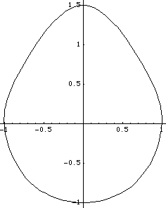
Out[36]= |  |
If it were desired to use this cam profile in a Modeler2D model with a circular cam follower, the following constraint syntax could be used. This constraint implies that the cam is on body 2, the circular follower is on the origin of body 3 and has a radius of 0.2, the constraint is constraint 4, and the initial guess for the cam parameter s is 2.0. Here is a cam constraint that uses a splined cam.
Out[37]= |  |
6.1.6 Rolling ContactIn order to have rolling contact between two cams, the arc length along the cam profile must be known as a function of the cam's controlling parameter. For cams that are built up from a sequence of piecewise continuous analytic functions, such as those shown in Section 6.1.1, it is often possible to build up a similar function that exactly represents the arc length of the cam. If a SplineFunction cam was used, the arc length cannot be explicitly stated, but Mech provides a function for approximating the arc length with another cubic spline. A spline utility. Example MechanismThe following example models a snail-shaped cam profile rolling on a stationary line. The cam is defined with a SplineFunction, and it is the single moving body in the mechanism. Note how the EndConditions option for SplineFit is used to specify the direction vector at the ends of the spline. Here are data points for a snail profile. SplineFit is applied to the data.
Out[39]= |  |
Here is a plot of the spline.
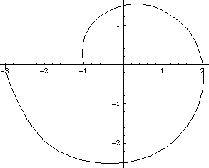
Out[40]= |  |
To constrain the snail-wheel to be in rolling contact, the arc length function of both contacting surfaces must be known. Since one of the two surfaces in this model is flat and has a trivial arc length function, only the arc length function of the snail-wheel must be determined. The Mech ArcLength function may work quite slowly, because it involves numerically integrating each segment of the SplineFunction object. Here is the arc length function of the snail spline.
Out[41]= |  |
ConstraintsThe snail-wheel is modeled with just three constraints. A CamToLine1 constraint places the snail-wheel in contact with the surface of the ground. Note the initial guess for the cam parameter s that sets the initial contact point at the bottom of the cam.A RotationLock1 constraint controls the angular orientation of the snail-wheel.A Constraint sets the arc length along the snail-wheel equal to the arc length along the flat surface. The arc length along the flat surface is simply the X coordinate of the cam contact point.Names are defined for each body. Here are the snail-wheel constraints. Reasonable initial guesses are set for the snail-wheel. Now we run the model at three positions.
Out[46]= |  |
Snail-wheel graphic at each solution point.
  
Analytic Snail-WheelIn fact, this particular mechanism could have been modeled without the use of SplineFunction at all. The snail-wheel cam profile can be built from analytic functions and its arc length can be found using Mathematica's symbolic integration capability. Here is the definition of an analytic snail-wheel.
Out[47]= |  |
Here is the exact arc length function of the snail-wheel.
Out[48]= | 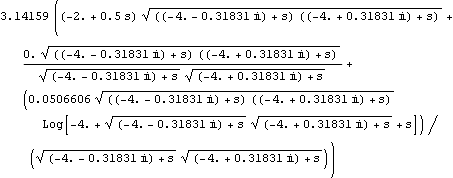 |
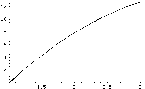
Here is a plot of the exact arc length function and the approximate arc length function, normalized to the same parameter scale and offset.
Out[49]= |  |
6.1.7 Fourier CamsAnother method of modeling arbitrary cam profiles is by approximating the cam profile with a Fourier series of sine and cosine functions. This method guarantees a continuously differentiable cam profile and also may evaluate more quickly than a SplineFunction object, provided only a relatively small number of terms are retained. One disadvantage of a Fourier series based cam profile is that it does not pass exactly through the data points used to generate it.
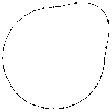
The following example uses a series of points in Cartesian coordinates that are to lie on the surface of a closed cam profile. The profile has a protruding lobe for 1/4 of a turn and is approximately circular with a radius of 3.0 for the next 3/4 of a turn. The built-in Mathematica Fourier function is used to generate the Fourier series. Here is the data to be transformed. Fourier is used to transform the data. Note that the zero-frequency term in each series must be divided by two to map correctly back into the time domain with Sin and Cos functions. Here are the first 10 terms of the approximate periodic function. Here is a plot of the Fourier profile along with the data points.
Out[57]= |  |
6.1.8 Cam Constraints within a Multistage ConstraintWhen a cam constraint is used within a TimeSwitch or StageSwitch function, the extra degrees of freedom that are introduced by the cam constraint must be dealt with when the cam constraint is not active. The following example shows how a TimeSwitch constraint might be used with a Modeler2D CamToPlane1 constraint. Here is an example of a TimeSwitch with a cam constraint. When the value of time exceeds 2.5 the one mechanical degree of freedom that was constrained by CamToPlane1 is constrained by RelativeAngle1, while the values of the two cam surface parameters alpha and beta are constrained to be equal to two constants.
If this technique were not used, the values of alpha and beta would be unconstrained after T = 2.5 and the model would not run. 6.1.9 Involute GearsA single pair of involute gear teeth can be modeled with Modeler2D as a pair of cam surfaces. Modeler2D provides a function for generating the involute profiles based on the standard gear tooth specifications. The involute gear tooth function. An option for Involute. The following example uses two gear tooth loci (functions of the symbols g1 and g2) located on a pair of mating gears. Note that the coordinates of the center point and the rotation angle of the involute are given in local coordinates. The tooth loci are not placed onto their respective bodies until they are put into Modeler2D point objects. Here is a pair of tooth loci.
Out[60]= |  |
Four constraints are used to model the two gear teeth. A Revolute2 constraint forces the center of gear 1 to be located at {0, 0}. A RotationLock1 constraint rotates gear 1. A Revolute2 constraint forces the center of gear 2 to be located at {12, 0}. A CamToCam1 constraint is used to enforce the contact of the gear teeth.Here are the involute gear model constraints. The model is run at T = 0.01.
Out[65]= |  |
Here are the two gear teeth.
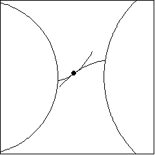
Note that the angular velocity ratio of the two gears is equal to the ratio of the radii of the base circles.
Out[66]= |  |
Undocumented Graphics GenerationThe following inputs generate the graphics in this section. These Modeler2D commands are defined in Chapter 3. Cam-Follower MechanismSnail-WheelGear Teeth3D Cam-Follower Mechanism
|