WOLFRAM SYSTEM MODELER
AutopilotPIDTuneExample of tuning autopilot PID controllers |
|
Diagram
Wolfram Language
In[1]:=
SystemModel["Aircraft.Examples.AutopilotPIDTune"]
Out[1]:=
Information
Tuning of Autopilot PID controllers
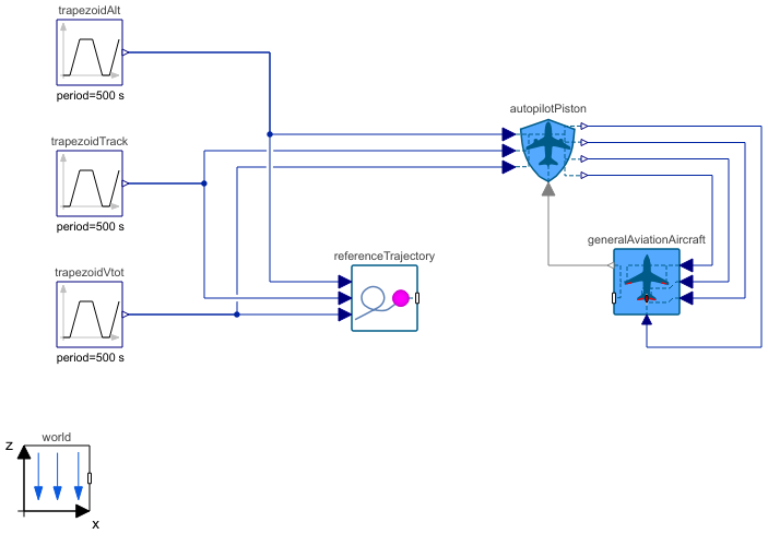
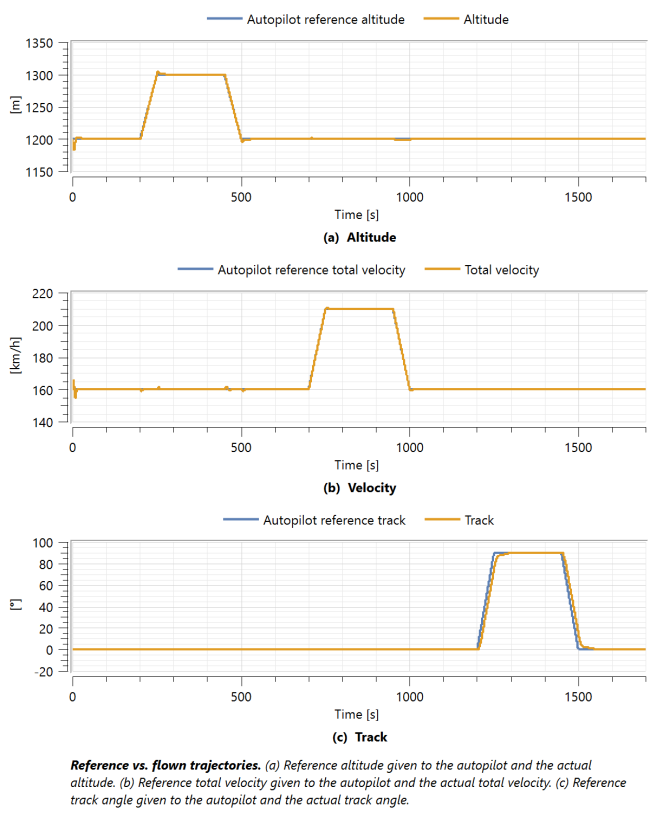
In this example, the gains of the six PID controllers found in the autopilot model can be adjusted to see how they affect the aircraft's ability to follow the given reference flight trajectory. The default plot shows the altitude, velocity and track of the reference trajectory. It consists of trapezoidal cycles which test the response to ramps in both directions individually for the three trajectory variables, as well as the actual trajectory variables. The ramp signals are well apart from each other to let the aircraft return to stable state state after each ramp. This reference trajectory will also allow studying how the perturbations in one reference trajectory variable will cause disturbances for the aircraft in following the other two reference trajectory variables [2].
This example has four different control panels for altitude, velocity, track and sideslip angle control to let the user explore how the adjustments in the PID controller gains change the response to the perturbations in the reference trajectory. Additionally, the base values of the altitude and velocity as well as the height of the trapezoids can be adjusted in the control panels to study the flight in different flight conditions and the response to different magnitudes of the perturbations in the reference trajectory variables.
The example also includes the VisualizationPoint component, which will visualize and draw the given reference trajectory as a 3D path in the animation for better visualization of the deviation of the aircraft from the reference trajectory in real time. In the animation, it becomes apparent that the current method of controlling the aircraft will result in a large deviation from the lateral position of the ReferenceTrajectory component after different track angles are applied. Additionally, as the reference velocity is increased, the aircraft will fall slightly behind the ReferenceTrajectory. This demonstrates that currently the lateral position of the aircraft is not controlled, only the velocity and track angles. However, the vertical position is directly controlled with the reference altitude.
[1] Erä-Esko, N. (2022). Development and Use of System Modeler 6DOF Flight Mechanics Model in Aircraft Conceptual Design. Available at: modelica://Aircraft/Resources/Documents/EraeEskoThesis.pdf.
Parameters (6)
| startAlt |
Value: 1200 Type: Height (m) Description: Initial altitude |
|---|---|
| startVtot |
Value: 44.4444444444444 Type: Velocity (m/s) Description: Initial total velocity |
| altAmplitude |
Value: 100 Type: Height (m) Description: Altitude amplitude |
| vTotAmplitude |
Value: 13.8888888888889 Type: Velocity (m/s) Description: Total velocity amplitude |
| trackAmplitude |
Value: 1.5707963267949 Type: Angle (rad) Description: Track amplitude |
| initialLatPosition |
Value: {1, 1} Type: Position[2] (m) Description: Initial lateral position of the aircraft (x and y coordinates in world frame) |
Components (7)
| trapezoidAlt |
Type: Trapezoid Description: Trapezoid signal for reference total velocity (amplitude in m) |
|
|---|---|---|
| trapezoidTrack |
Type: Trapezoid Description: Trapezoid signal for reference track (amplitude in deg) |
|
| trapezoidVtot |
Type: Trapezoid Description: Trapezoid signal for reference total velocity (amplitude in km/h) |
|
| autopilotPiston |
Type: AutopilotPiston Description: Autopilot for light aircraft with piston engine propulsion |
|
| generalAviationAircraft |
Type: GeneralAviationAircraft Description: Model of a general aviation aircraft |
|
| world |
Type: World Description: World coordinate system used in aircraft libray |
|
| visualization |
Type: VisualizationPoint Description: Draws the reference 3D trajectory as a parametric curve |