WOLFRAM SYSTEMMODELER
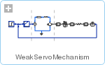
WeakServoMechanismA servo mechanism with a weak axis |
|
Diagram

Wolfram Language
In[1]:=

SystemModel["IntroductoryExamples.MultiDomain.WeakServoMechanism"]
Out[1]:=
Information
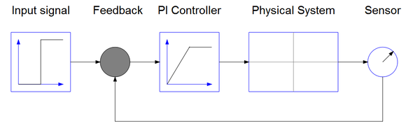
The structure of the control system is shown in the schematic picture below. It consists of an input signal, a sensor, a feedback loop, and a regulator. The physical system consists of the gear and axis system described in DC Motor and Weak Axis. Since the physical system has negative static gain the PI gain also has to be negative.
In the stiff servo mechanism example it is shown how different controller gains affect the response. After selecting a gain k = 1.5 for both the stiff and weak axis systems we can compare the results:
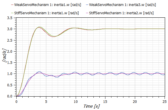
As seen the controller design made using the stiff axis model performs well also when the more accurate weak axis is used in simulations.
For a step by step tutorial see Multidomain—A Servo Mechanism.
Components (14)
| ground1 |
Type: Ground Description: |
|
|---|---|---|
| inertia1 |
Type: Inertia Description: |
|
| idealGear1 |
Type: IdealGear Description: |
|
| EMF1 |
Type: EMF Description: |
|
| signalVoltage1 |
Type: SignalVoltage Description: |
|
| feedback1 |
Type: Feedback Description: |
|
| step1 |
Type: Step Description: |
|
| resistor1 |
Type: Resistor Description: |
|
| inductor1 |
Type: Inductor Description: |
|
| speedSensor1 |
Type: SpeedSensor Description: |
|
| inertia2 |
Type: Inertia Description: |
|
| spring1 |
Type: Spring Description: |
|
| inertia3 |
Type: Inertia Description: |
|
| PI1 |
Type: PI Description: |