WOLFRAM SYSTEM MODELER
MotorMotor model including current controller of r3 motors |
|
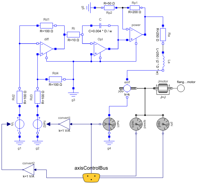
Diagram
Wolfram Language
In[1]:=
SystemModel["Modelica.Mechanics.MultiBody.Examples.Systems.RobotR3.Utilities.Motor"]
Out[1]:=

Information
This information is part of the Modelica Standard Library maintained by the Modelica Association.
Default values are given for the motor of joint 1. The input of the motor is the desired current (the actual current is proportional to the torque produced by the motor).
Parameters (6)
| J |
Value: 0.0013 Type: Inertia (kg⋅m²) Description: Moment of inertia of motor |
|---|---|
| k |
Value: 1.1616 Type: Real Description: Gain of motor |
| w |
Value: 4590 Type: Real Description: Time constant of motor |
| D |
Value: 0.6 Type: Real Description: Damping constant of motor |
| w_max |
Value: 315 Type: AngularVelocity (rad/s) Description: Maximum speed of motor |
| i_max |
Value: 9 Type: Current (A) Description: Maximum current of motor |
Connectors (2)
| flange_motor |
Type: Flange_b Description: One-dimensional rotational flange of a shaft (non-filled circle icon) |
|
|---|---|---|
| axisControlBus |
Type: AxisControlBus Description: Data bus for one robot axis |
Components (27)
| Vs |
Type: SignalVoltage Description: Generic voltage source using the input signal as source voltage |
|
|---|---|---|
| power |
Type: IdealOpAmp Description: Ideal operational amplifier (norator-nullator pair) |
|
| diff |
Type: IdealOpAmp Description: Ideal operational amplifier (norator-nullator pair) |
|
| emf |
Type: RotationalEMF Description: Electromotoric force (electric/mechanic transformer) |
|
| La |
Type: Inductor Description: Ideal linear electrical inductor |
|
| Ra |
Type: Resistor Description: Ideal linear electrical resistor |
|
| Rd2 |
Type: Resistor Description: Ideal linear electrical resistor |
|
| C |
Type: Capacitor Description: Ideal linear electrical capacitor |
|
| OpI |
Type: IdealOpAmp Description: Ideal operational amplifier (norator-nullator pair) |
|
| Ri |
Type: Resistor Description: Ideal linear electrical resistor |
|
| Rd1 |
Type: Resistor Description: Ideal linear electrical resistor |
|
| Rp1 |
Type: Resistor Description: Ideal linear electrical resistor |
|
| Rp2 |
Type: Resistor Description: Ideal linear electrical resistor |
|
| Rd4 |
Type: Resistor Description: Ideal linear electrical resistor |
|
| hall2 |
Type: SignalVoltage Description: Generic voltage source using the input signal as source voltage |
|
| Rd3 |
Type: Resistor Description: Ideal linear electrical resistor |
|
| g1 |
Type: Ground Description: Ground node |
|
| g2 |
Type: Ground Description: Ground node |
|
| g3 |
Type: Ground Description: Ground node |
|
| hall1 |
Type: CurrentSensor Description: Sensor to measure the current in a branch |
|
| g4 |
Type: Ground Description: Ground node |
|
| g5 |
Type: Ground Description: Ground node |
|
| phi |
Type: AngleSensor Description: Ideal sensor to measure the absolute angle of flange |
|
| speed |
Type: SpeedSensor Description: Ideal sensor to measure the absolute angular velocity of flange |
|
| Jmotor |
Type: Inertia Description: 1D-rotational component with inertia |
|
| convert1 |
Type: Gain Description: Output the product of a gain value with the input signal |
|
| convert2 |
Type: Gain Description: Output the product of a gain value with the input signal |
Used in Components (1)
|
Modelica.Mechanics.MultiBody.Examples.Systems.RobotR3.Utilities Axis model of the r3 joints 4,5,6 |