WOLFRAM SYSTEM MODELER
CylindricalBeamElementClass containing beam elements based on Euler–Bernoulli beam theory |
|
Wolfram Language
In[1]:=
SystemModel["RotatingMachinery.Shafts.SingleFiniteElements.CylindricalBeamElement"]
Out[1]:=
Information
This model is an extended version of an Euler–Bernoulli Beam element. In addition to the Euler–Bernoulli Beam element, axial and twisting deformation is also taken into account. Background theory can be found in [1].
The axial direction of the beam is by default in the z direction, i.e. [3]-direction. See the following figure.
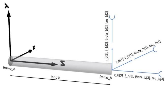
Figure 1: Cylindrical beam element.
The forces to deformation relation can be written as:
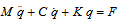
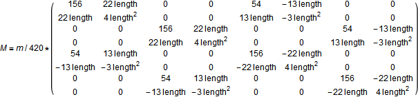
where the mass matrix M can be written as:
the damping matrix C can be written as:

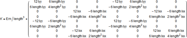
the stiffness matrix K can be written as:
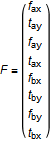
The load vector F, which describes loads and moments in the two directions that are not the axial for the beam (i.e. x and y axes), can be written as:
The deformation vector q can be written as:
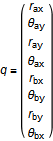
where f is forces, t is the bending moment, r is displacement, and θ is the rotation angle. The index a refers to frame_a, and b refers to frame_b. The x, y and z directions correspond to the Modelica notation [1], [2] and [3], respectively. For instance, fax is the force in direction [1] on flange a and tby is the bending moment around axis [2] on flange b.
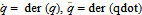
The velocities and accelerations become:
In addition to the Euler–Bernoulli Beam element, axial and twisting deformation is also taken into account. The axial deformation becomes:


Parameters:
length= Length of beamdiameter= Diameter of beaminnerDiameter= Inner diameter of beamheight=Height of beam (y axis)density= Density of beam materialEmod= Young’s modulusG= Element material modulus of rigidity (Shear modulus)alpha= Rayleigh constant, i.e. material damping proportional to the stiffness matrixenforceStates_a= true, if absolute variables of frame_a shall be used as states (StateSelect.always)enforceStates_b= true, if absolute variables of frame_b shall be used as states (StateSelect.always)resolveInFrame=RotatingMachinery.Components.Shafts.Components.Types.ResolveInFrame.frame_a, if variables of the beam shall be resolved inframe_a
A vibration due to material damping is frequency dependent; i.e. alpha needs to be adjusted depending which mode is studied.
As a rule of thumb, enforceStates_a is false for all elements and enforceStates_b is true for all elements until it is rooted, i.e. normally the last element. Several examples describe this; see RotatingMachinery.Examples.Shafts.
Normally, the default value for resolveInFrame is sufficient. If the model is built from "left to right", i.e. from frame_a to frame_b, this value should be the default. If a beam is connected only in frame_b, this value might have to be changed to frame_b instead.
References
[1] Wikipedia. "Euler-Bernoulli Beam." https://en.wikipedia.org/wiki/Euler%E2%80%93Bernoulli_beam_theory.
[2] Adams, M. L . Rotating Machinery Vibration: From Analysis to Troubleshooting (2nd ed.). CRC Press, 2010.
Parameters (22)
| length |
Type: Length (m) Description: Beam length |
|---|---|
| density |
Value: 7850 Type: Density (kg/m³) Description: Density of beam material |
| Emod |
Value: 210000000000.0 Type: ModulusOfElasticity (Pa) Description: Young's Modulus |
| G |
Value: 80000000000.0 Type: ShearModulus (Pa) Description: Element material modulus of rigidity (Shear modulus) |
| alpha |
Value: 1 / 1000 Type: Real Description: Rayleigh constant |
| enforceStates_a |
Value: false Type: Boolean Description: = true, if absolute variables of frame_a shall be used as states (StateSelect.always) |
| enforceStates_b |
Value: false Type: Boolean Description: = true, if absolute variables of frame_b shall be used as states (StateSelect.always) |
| A |
Value: Modelica.Constants.pi * ((diameter / 2) ^ 2 - (innerDiameter / 2) ^ 2) Type: Area (m²) Description: Beam cross sectional area |
| m |
Value: A * density * length Type: Mass (kg) Description: Mass of element |
| Ixx |
Value: Modelica.Constants.pi * (diameter ^ 4 - innerDiameter ^ 4) / 64 Type: SecondMomentOfArea (m⁴) Description: Area moment of inertia |
| Iyy |
Value: Modelica.Constants.pi * (diameter ^ 4 - innerDiameter ^ 4) / 64 Type: SecondMomentOfArea (m⁴) Description: Area moment of inertia |
| Jp |
Type: SecondPolarMomentOfArea (m⁴) Description: Polar moment of inertia |
| Ip |
Value: 0.5 * m * ((diameter / 2) ^ 2 - (innerDiameter / 2) ^ 2) Type: MomentOfInertia (kg⋅m²) Description: Mass polar moment of inertia |
| diameter |
Value: 0.02 Type: Diameter (m) Description: Outer radius of beam |
| innerDiameter |
Value: 0 Type: Diameter (m) Description: Inner radius of beam |
| I0 |
Value: Modelica.Constants.pi * (diameter ^ 4 - innerDiameter ^ 4) / 64 Type: SecondMomentOfArea (m⁴) Description: Area moment of inertia |
| K |
Value: Emod / length ^ 3 * {{12 * Iyy, 6 * length * Iyy, 0, 0, -12 * Iyy, 6 * length * Iyy, 0, 0}, {6 * length * Iyy, 4 * length ^ 2 * Iyy, 0, 0, -6 * length * Iyy, 2 * length ^ 2 * Iyy, 0, 0}, {0, 0, 12 * Ixx, -6 * length * Ixx, 0, 0, -12 * Ixx, -6 * length * Ixx}, {0, 0, -6 * length * Ixx, 4 * length ^ 2 * Ixx, 0, 0, 6 * length * Ixx, 2 * length ^ 2 * Ixx}, {-12 * Iyy, -6 * length * Iyy, 0, 0, 12 * Iyy, -6 * length * Iyy, 0, 0}, {6 * length * Iyy, 2 * length ^ 2 * Iyy, 0, 0, -6 * length * Iyy, 4 * length ^ 2 * Iyy, 0, 0}, {0, 0, -12 * Ixx, 6 * length * Ixx, 0, 0, 12 * Ixx, 6 * length * Ixx}, {0, 0, -6 * length * Ixx, 2 * length ^ 2 * Ixx, 0, 0, 6 * length * Ixx, 4 * length ^ 2 * Ixx}} Type: Real[8,8] Description: Page 87, Concepts and applications of finite element analysis, Robert Cook |
| Kz |
Value: Emod * A / length * {{1, -1}, {-1, 1}} Type: Real[2,2] Description: Page 88-89, Concepts and applications of finite element analysis, Robert Cook |
| Kthetaz |
Value: G * Jp / length * {{1, -1}, {-1, 1}} Type: Real[2,2] Description: Page 89 in Rotating Machinery Vibration, Maurice length. Adams, JR.S |
| M |
Value: m / 420 * {{156, 22 * length, 0, 0, 54, -13 * length, 0, 0}, {22 * length, 4 * length ^ 2, 0, 0, 13 * length, -3 * length ^ 2, 0, 0}, {0, 0, 156, 22 * length, 0, 0, 54, -13 * length}, {0, 0, 22 * length, 4 * length ^ 2, 0, 0, 13 * length, -3 * length ^ 2}, {54, 13 * length, 0, 0, 156, -22 * length, 0, 0}, {-13 * length, -3 * length ^ 2, 0, 0, -22 * length, 4 * length ^ 2, 0, 0}, {0, 0, 54, 13 * length, 0, 0, 156, -22 * length}, {0, 0, -13 * length, -3 * length ^ 2, 0, 0, -22 * length, 4 * length ^ 2}} Type: Real[8,8] Description: Page 304, Concepts and applications of finite element analysis, Robert Cook |
| Mz |
Value: {{m / 2, 0}, {0, m / 2}} Type: Real[2,2] Description: Page 304, Concepts and applications of finite element analysis, Robert Cook |
| Mthetaz |
Value: {{Ip / 3, Ip / 6}, {Ip / 6, Ip / 3}} Type: Real[2,2] Description: Page 88-89 in Rotating Machinery Vibration, Maurice length. Adams, JR.S |
Connectors (3)
| frame_a |
Type: Frame_a Description: Coordinate system fixed to the component with one cut-force and cut-torque |
|
|---|---|---|
| frame_b |
Type: Frame_b Description: Coordinate system fixed to the component with one cut-force and cut-torque |
|
| frame_resolve |
Type: Frame_resolve Description: Coordinate system fixed to the component used to express in which coordinate system a vector is resolved (non-filled rectangular icon) |
Components (3)
| world |
Type: World Description: World coordinate system + gravity field + default animation definition |
|
|---|---|---|
| R_a |
Type: Orientation Description: Orientation object defining rotation from a frame 1 into a frame 2 |
|
| R_b |
Type: Orientation Description: Orientation object defining rotation from a frame 1 into a frame 2 |
Used in Components (1)
|
RotatingMachinery.Shafts.SingleFiniteElements Class with a flexible cylindrical beam |