Deploy code that will balance a ball on a beam
Introduction
The ball on the horizontal beam is unstable. Due to the effects of gravity the ball will roll to one end of the beam and the beam will not stay in the horizontal position. However using a motor we can control the beam’s orientation and the ball’s position.
The position of the ball is measured by an IR distance sensor. The beam is controlled by a servo motor. The operating voltage required by the motor is maintained by a power converter. The desired position of the ball is specified using a potentiometer. The controller, running on an Arduino Uno, measures the potentiometer and IR sensor values and sends an appropriate signal to the servo motor.
We will start by computing a model of the system. Then we will obtain the calibration for both the IR sensor and the servo motor. We will design three controllers: a PID controller, a pole-placement controller, and an integral controller and compare their responses.
Parts
Makeblock servo motor [link]
Shaft connector [link]
Makeblock Servo motor bracket pair [link]
Makeblock Beam0824-320 pair [link]
Makeblock Beam0824-192 pair [link]
Makeblock Beam0824-160 pair [link]
Makeblock Beam0824-144 [link]
Makeblock Beam0824-096 pair [link]
Makeblock Bracket 3x3 pair [link]
7 M4x22mm screws [link], 30 M4x14mm screws [link], 5 M4x8mm screws [link], 14 M4 nuts [link], and 3 4x7x2 plastic rings [link]

3D printed motor flange-to-beam female connector [link]
3D printed motor flange-to-beam male connector [link]
2 3D printed beam ends [link]
IR distance sensor [link] with 3-pin female cable [link] and housing [link]
Arduino Uno [link]
Potentiometer [link]
Protoshield [link]
Male header pins [link]
USB cable [link]
Adjustable DC&DC Power Converter [link]
Power supply adapter [link]
Misc standoffs [link]
A heavy weight or a clamp
Adhesive mounting squares [link]
A pin-pong ball

Assembly
Screw 2 0824-096 and 2 0824-160 beams together using 4 M4x14 screws to create the base. (Fix adhesive squares to the bottom if there is a possibilty of chattering during operation.)
Screw a 3x3 bracket to each 0824-160 beam using 2 M4x14 screws and 2 nuts.
Screw a 0824-192 beam to each 0824-160 beam using 2 M4x22 screws and 2 nuts.
Screw the 0824-144 beam to the top of the 2 0824-192 beams using 4 M4x14 screws.
Screw a motor bracket to the 0824-144 beam using 2 M4x14 screws and 2 nuts.
Screw together the motor, motor flange, shaft connector, and the flange-to-beam female connector using 1 M4x22 screws in the center and 2 M4x14 screws.
Screw the motor assembly to the motor bracket using 3 M4x8 mm screws and 3 plastic rings.
After inserting the 3-pin female cable in to IR distance sensor on one end and the housing on the other, screw the sensor onto one of the beam ends using 2 M4x8 screws.
On one of the 0824-320 beams create a scale with markings.
Screw the beam ends to the 2 0824-320 beams using 8 M4x14 screws.
Screw the flange-to-beam male connector the 0824-320 beam without the markings using 2 M14x22 screws and 2 nuts.
Screw the bracket onto one of the 0824-320 beams on the IR sensor side using 2 M4x14 screws and 2 nuts.
Insert the male connector holding the beam onto the female conenctor on the motor assembly, and clamp the setup using the weight.
Wire the electrical connections using a protoshield board or a breadboard. Before connecting the the power converter make sure that the output voltage (VOUT) is set to 6V.
Raise the Arduino using stand offs and stack the protoshield board on top of it
Connect the motor and sensor to the correct locations on the protoshield board.
Modeling
The ball and beam as viewed from the front.
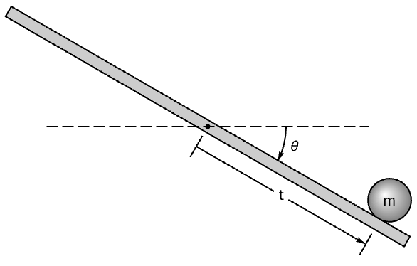
We will consider the angle specified to the servo motor as the control input. Thus along with ignoring the dynamics of the motor, we can also ignore the mass of the beam.
The Lagrangian is computed as the difference between the kinetic and potential energies.
We will assume that the ball is a hollow sphere and that it rolls without slipping.
Use a linearizing feedback with control input u that will linearize the system.
The Lagrangian after including the additional assumptions and linearizing feedback.
The equation of motion.
The linear StateSpaceModel with u as input and r as output.
Sensor calibration
Embed the code that will read the IR sensor value and output it on the serial channel.
Open a connection to the microcontroller.
A function to parse the incoming data.
A task to read the incoming data.
Place the ball at various locations on the beam and record the sensor reading.
The sensor data.
After acquiring sufficient data points stop the task and close the connection.
Fit a nonlinear model to the data.
Compare the data and the model.
Restructure the model as a NonlinearStateSpaceModel.
Servo calibration
We will use the Arduino servo library to control the motor.
The servo output channel.
The ‘angle’ of the servo specified in the library takes a value from 0 to 180. This is not the same as θ used in the model. We will need to determine the map between θ and ‘angle’.
To do this, we will create a model with the servo output as a specific ‘angle’ value.
When it is embedded to the microcontroller the beam will orient itself accordingly.
Measure and record the resulting θ. Repeat the process to obtain several data points.
Fit a nonlinear model to the data.
Compare the data and the model.
Restructure the model as a NonlinearStateSpaceModel.
If θ is large the beam could strike the table. Also as the controller brings back the beam from a large θ value the, the ball could jump off the beam. To prevent this we put clamps on how much the servo can rotate from the equilibrium value of θ==0.
Create a model for the clamp.
Misc components
We will now create the model of some of the other components that we will be using.
The reference position is set by a potnentiometer that reads from 0 to 5V. Create a model that maps it to - 6 cm to 6 cm.
Restructure the model as a NonlinearStateSpaceModel.
The model of the comparator to compare the reference and actual positions.
For simuation we will also need a continuous-time comparator.
The arc sin function asin in the AVR-Libc library will give an error if the argument is not in the correct range. A model that gracefully handles the ArcSin computation.
Another model that ensures the arc sin argument is in the correct range.
The microcontroller specifications for the controller code.
The microcontroller, port, and library specifications.
The sampling period.
PID controller design
Design a PID controller with a filtered derivative part.
The closed-loop system.
Simulate the closed-loop system.
The simulation shows that is takes a while to settle down. Looking at the eigenvalues of the system we see that some are close to the imaginary axis.
The feedback controller.
The feedforward filter.
Discretize the pid controller.
PID controller deployment
The complete PID controller.
Load the package.
Embed the controller.
Pole-placement controller design
We will use pole-placement to move the poles further into the left half-plane. Because this uses full state-feedback and only the position r is measured, we also need to an estimator. In addition a feedforward term is needed for the controller to track the reference signal.
Compute the feedback gains using StateFeedbackGains.
Compute the estimator gains EstimatorGains.
The state estimator.
The feedback controller.
The feedforward controller.
The structure of the controller and plant.
The closed-loop system.
The eigenvalues of the closed-loop system.
Verify that they are at the designed locations.
Discretize the controllers.
Pole-placement deployment
The complete pole-placement controller.
Embed the controller.
Integral controller design
Augment the state equations with the integral of the error.
A set of optimal gains that heavily penalize the error.
The eigenvalues of the closed-loop system.
The feedforward controller.
The feedback controller.
The structure of the controller and plant.
The closed-loop system.
Compute the eigenvalues.
Discretize the controllers.
Integral controller deployment
The complete integral controller.
Conclusions
The simulations of the step reponses of the linear closed-loop systems with the three controllers shows the pole-placement controller performing better than the others.
As expected the PID controller does not perform well with the double integrator system. In the actual physical system it is characterized by large settling times and overshoots. It had good steady-state response.
The pole-placement controller worked well, but it perfommed very poorly on a different setup with a different IR sensor and motor.
Overall, the integral controller worked the best in terms of transient, steady-state, and disturbance response. It was robost enough to maintain good performance when the sensors and motor was changed.
More things to try
- Simulate the disturbance responses.
- Try different PID tuning rules.
- Try other feedback and estimator gains.
- Investigate the difference when the nonlinear ArcSin element is removed.
- Introduce antiwindup control.