AdjacentMeshCells[mr,cellspec,d]
メッシュ mr 内の cellspec で指定されたセルに隣接する次元 d のセルを与える.
AdjacentMeshCells
AdjacentMeshCells[mr,cellspec,d]
メッシュ mr 内の cellspec で指定されたセルに隣接する次元 d のセルを与える.
詳細
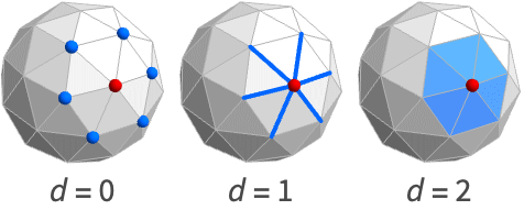
- AdjacentMeshCellsは隣接セルとしても知られている.
- 主に,メッシュにおけるセルの隣接性や位相情報を得るために使われる.
- AdjacentMeshCells[mr,cellspec,d]は,cellspec で指定されたセルに隣接する d 次元のセルに関連付けられたセルの指標リストを返す.
- 次のセル指定 cellspec を使うことができる.
-
{d,i} 次元 d で指標が i のセル {d,ispec} 次元 d で指標指定が ispec のセル {dspec,…} 次元が dspec で与えられるセル h[{i1,…}] 頭部が h で頂点指標が i1, …の明示的なセル {c1,c2,…} 明示的なセル ciのリスト - 指標指定 ispec には次の形式がある.
-
i セル指標 i {i1,i2,…} 指標が ikのセル All すべてのセル patt 指標がパターン patt にマッチするセル - 次元指定 dspec には次の形式がある.
-
d 明示的な次元 d All 0から領域の幾何次元までの全次元 patt パターン patt にマッチする次元
例題
すべて開く すべて閉じる例 (2)
ℛ = MengerMesh[1, MeshCellStyle -> {{0, 2} -> Red}]AdjacentMeshCells[ℛ, {0, 2}, 1]HighlightMesh[ℛ, %]pattern = {0, _ ? (# < 3&)};
ℛ = VoronoiMesh[RandomReal[1, {10, 2}], MeshCellStyle -> {pattern -> Red}];AdjacentMeshCells[ℛ, pattern, 2]HighlightMesh[ℛ, %]スコープ (5)
基本的な用法 (2)
ℛ = MeshRegion[{{0, 0, 0}, {2, 0, 0}, {2, 2, 0}, {0, 2, 0}, {1, 1, 2}},
{Tetrahedron[{{1, 2, 3, 5}, {1, 3, 4, 5}}]}]AdjacentMeshCells[ℛ, {0, 1}, 2]AdjacentMeshCells[ℛ, {_, 1}, 2]AdjacentMeshCells[ℛ, Line[{1, 2}], 2]AdjacentMeshCells[ℛ, {{0, 1}, {1, 2}}, 2]Table[AdjacentMeshCells[[image], {0, 1}, d], {d, {0, 1, 2, 3}}]メッシュ領域 (2)
2DにおけるMeshRegionのAdjacentMeshCells:
mesh = DelaunayMesh[RandomReal[1, {10, 2}], MeshCellStyle -> {{0, 1} -> Green}]AdjacentMeshCells[mesh, {0, 1}, 1]HighlightMesh[mesh, %]AdjacentMeshCells[[image], {0, 1}, 1]mesh = [image];AdjacentMeshCells[mesh, {0, 1}, 1]HighlightMesh[mesh, %]BoundaryMeshRegionのAdjacentMeshCells:
mesh = BoundaryMeshRegion[{{0, 0}, {3, 0}, {3, 3}, {0, 3}, {1, 1}, {2, 1}, {2, 2}, {1, 2}}, Line[{1, 2, 3, 4, 1}], Line[{5, 6, 7, 8, 5}], MeshCellStyle -> {{0, 1} -> Green}]AdjacentMeshCells[mesh, {0, 1}, 1]HighlightMesh[mesh, %]AdjacentMeshCells[[image], {0, 1}, 0]mesh = [image];AdjacentMeshCells[mesh, {0, 1}, 1]HighlightMesh[mesh, %]多角形と多面体 (1)
ℛ = Cube[];AdjacentMeshCells[ℛ, {0, 1}, 1]HighlightMesh[ℛ, %]ℛ = Simplex[{{0, 0, 1}, {1, 0, 0}, {1, 0, 1}, {1, 1, 1}}];AdjacentMeshCells[ℛ, {0, 1}, 1]HighlightMesh[ℛ, %]ℛ = Polyhedron[{{-0.85065080835204, 0., 1.1135163644116066}, {-0.2628655560595668, 0.8090169943749475,
1.1135163644116066}, {-0.42532540417602, 1.3090169943749475, 0.2628655560595668},
{-1.1135163644116066, 0.8090169943749475, -0.262865556059566 ...
{{1, 2, 3, 4, 5}, {6, 7, 1, 5, 8}, {9, 10, 6, 8, 11}, {12, 13, 9, 11, 14}, {4, 14, 11, 8, 5},
{3, 15, 12, 14, 4}, {16, 17, 10, 9, 13}, {18, 16, 13, 12, 15}, {19, 18, 15, 3, 2},
{20, 19, 2, 1, 7}, {17, 20, 7, 6, 10}, {16, 18, 19, 20, 17}}];AdjacentMeshCells[ℛ, {0, 1}, 1]HighlightMesh[ℛ, %]ℛ = Triangle[{{0, 0}, {1, 1}, {2, 0}}];AdjacentMeshCells[ℛ, {0, 1}, 1]HighlightMesh[ℛ, %]ℛ = Polygon[{{1, 0}, {1/2, Sqrt[3]/2}, {-1/2, Sqrt[3]/2}, {-1, 0}, {-1/2, -1/2*Sqrt[3]},
{1/2, -1/2*Sqrt[3]}}];AdjacentMeshCells[ℛ, {0, 1}, 1]HighlightMesh[ℛ, %]Line:
ℛ = Line[{{1, 0}, {2, 1}, {3, 0}, {4, 1}}];AdjacentMeshCells[ℛ, {0, 1}, 1]HighlightMesh[ℛ, %]アプリケーション (8)
基本的なアプリケーション (5)
Triangleの隣接メッシュセル:
mesh = [image];cells = AdjacentMeshCells[mesh, {0, 2}, 0]HighlightMesh[mesh, cells]Cubeの隣接メッシュセル:
mesh = [image];cells = AdjacentMeshCells[mesh, {0, 6}, 0]HighlightMesh[mesh, cells]MengerMeshの隣接メッシュセル:
mesh = MengerMesh[2, MeshCellStyle -> {{0, 6} -> Red}];cells = AdjacentMeshCells[mesh, {0, 6}, 0]HighlightMesh[mesh, cells]mesh = [image];cells = AdjacentMeshCells[mesh, {0, 12}, 0]HighlightMesh[mesh, cells]pts = RandomReal[1, {10, 2}];mesh = VoronoiMesh[pts, MeshCellStyle -> {{0, 12} -> Red}];cells = AdjacentMeshCells[mesh, {0, 12}, 0]HighlightMesh[mesh, cells]隣接クエリ (1)
AdjacentMeshCellsを使ってセル指標が{0,1}の点と連結するすべての点を求める:
AdjacentMeshCells[[image], {0, 1}, 0]多面体操作 (1)
AdjacentMeshCellsを使って立方体のDualPolyhedronを計算する:
cube = [image];faces = (Last /@ AdjacentMeshCells[cube, {0, #}, 2])& /@ Range[MeshCellCount[cube, 0]]pts = MeshCoordinates[cube];
fs = And@@@ MeshCells[cube, 2];
coords = Table[Mean[pts[[i]]], {i, fs}]dual = Polyhedron[coords, faces]Graphics3D[{Opacity[0.2], cube, dual}]位相操作 (1)
MeshConnectivityGraphを使ってメッシュが連結しているかどうかを調べる:
ConnectedMeshQ[mesh_] := Block[{a = {{0, 1}}, b},
While[b = Union[Join[a, AdjacentMeshCells[mesh, a, 0]]];b =!= a, a = b];
Length[a] == MeshCellCount[mesh, 0]
]Table[ConnectedMeshQ[i], {i, {[image], [image], [image], [image]}}]特性と関係 (2)
セル指標{d, k}は次元 d の k 番目のセルに対応する:
mesh = MeshRegion[{{0, 0}, {1, 0}, {2, 1 / 2}, {2, -1 / 2}}, {Line[{1, 2}], Line[{2, 3}], Line[{3, 4}], Line[{4, 2}]}]AdjacentMeshCells[mesh, {1, 2}, 1]AdjacentMeshCellsはMeshConnectivityGraphを使って求めることができる:
mesh = MeshRegion[{{0, 0, 0}, {2, 0, 0}, {2, 2, 0}, {0, 2, 0}, {1, 1, 2}}, {Tetrahedron[{1, 2, 3, 5}], Tetrahedron[{1, 3, 4, 5}]}]MeshConnectivityGraph[mesh, {0, 2}]AdjacencyList[%, {0, 1}]AdjacentMeshCells[mesh, {0, 1}, 2]おもしろい例題 (1)
メンガーメッシュのAdjacentMeshCells:
g = MengerMesh[4];
spec = Thread[List[0, RandomSample[Range[MeshCellCount[g, 0]], 35]]];
cells = AdjacentMeshCells[g, spec, 0];MeshRegion[g, MeshCellStyle -> Join[{spec -> Red}, Thread[cells -> Green], {{_ ? (# > 0&), All} -> White}], ImageSize -> 200]関連するガイド
テキスト
Wolfram Research (2020), AdjacentMeshCells, Wolfram言語関数, https://reference.wolfram.com/language/ref/AdjacentMeshCells.html.
CMS
Wolfram Language. 2020. "AdjacentMeshCells." Wolfram Language & System Documentation Center. Wolfram Research. https://reference.wolfram.com/language/ref/AdjacentMeshCells.html.
APA
Wolfram Language. (2020). AdjacentMeshCells. Wolfram Language & System Documentation Center. Retrieved from https://reference.wolfram.com/language/ref/AdjacentMeshCells.html
BibTeX
@misc{reference.wolfram_2026_adjacentmeshcells, author="Wolfram Research", title="{AdjacentMeshCells}", year="2020", howpublished="\url{https://reference.wolfram.com/language/ref/AdjacentMeshCells.html}", note=[Accessed: 07-September-2026]}
BibLaTeX
@online{reference.wolfram_2026_adjacentmeshcells, organization={Wolfram Research}, title={AdjacentMeshCells}, year={2020}, url={https://reference.wolfram.com/language/ref/AdjacentMeshCells.html}, note=[Accessed: 07-September-2026]}