WOLFRAM SYSTEM MODELER
LinearAttitudePIDControl the attitude of the quadrotor through PID controllers |
|
Diagram
Wolfram Language
In[1]:=
SystemModel["Aircraft.ControlSystems.MultiRotorControllers.LinearAttitudePID"]
Out[1]:=
Information
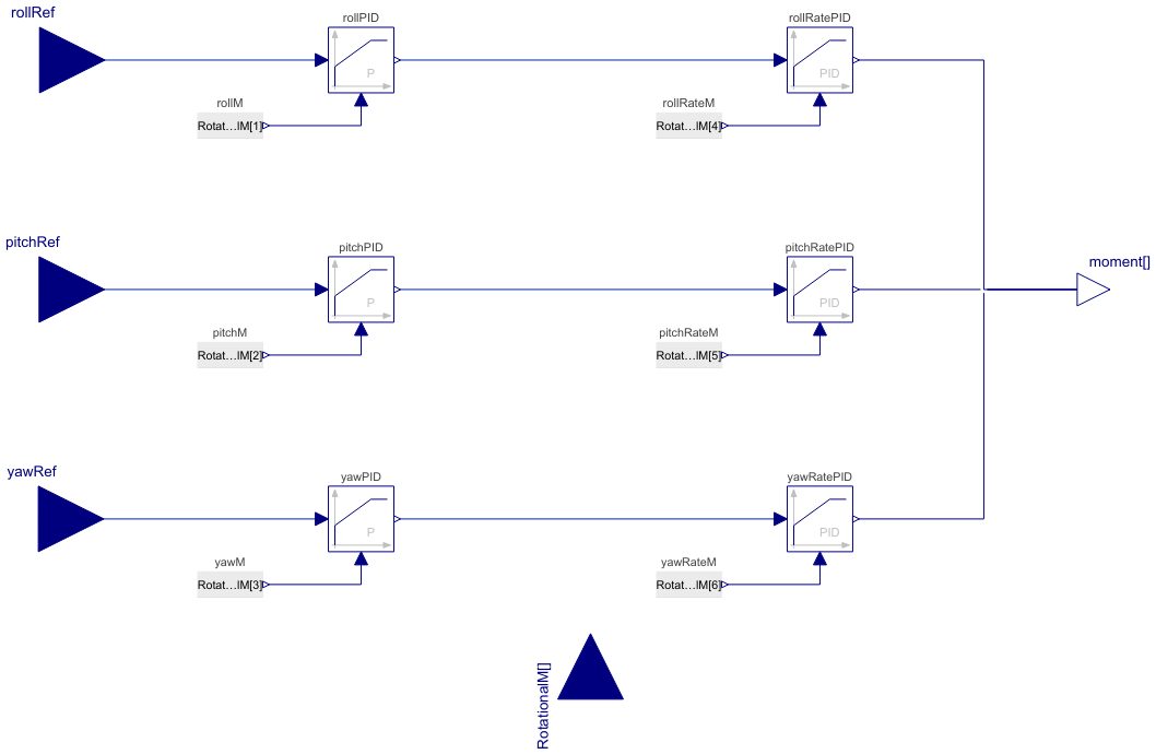
The primary objective of the control design described here is to achieve stable positioning for the unmanned aerial vehicle (UAV) by maintaining a constant set point. To overcome the inherent underactuation challenges associated with vectored-thrust UAVs, a hierarchical control strategy that effectively utilizes the attitude dynamics to stabilize the translational dynamics is employed.
The attitude measurments of the sensors are in the quadrotor body reference frame.
The attitude controller takes the reference rotation angles (φref, θref, and ψref) as its inputs and produces a vector representing the moment change in roll, pitch and yaw.
Figure 1 depicts the block diagram of the attitude controller, which employs a cascade control structure utilizing P-PID controllers for the longitudinal, lateral and directional control channels. For angle control, the reference angle is subtracted from the quadrotor's measured angle to obtain the error, which is then passed to a proportional controller. The output of the proportional controller corresponds to the desired angular rate. Subsequently, the error in angular rate is computed by comparing it with the measured angular rate, and this error is fed into a LimPID controller. Finally, the LimPID controller calculates the moment change, which is then sent to the Mixer. Within the Mixer, the necessary voltage commands for each DC motor are determined through force and moment allocation. [1]

Figure 1: Controller block diagram.
LimPID
The LimPID controller can be finely adjusted by modifying its proportional gain, integrator, derivative time constants and saturation limit. The saturation limit can be configured within the constraints defined by yMax and yMin, taking into account model limitations such as actuator deflection limits or motor RPM. Once the controller type in LimPID is selected, a combination of proportional, derivative and integral controllers can be configured to meet the desired control objectives.
Note: The controller gains should be tuned based on the specific quadrotor and mission requirements.
[1]: Giurato, M. (2020). Design, integration and control of multirotor UAV platforms.
Parameters (12)
| propGainRollPID |
Value: 10 Type: Real Description: Gain of controller (PIDRoll.k) |
|---|---|
| propGainPitchPID |
Value: 10 Type: Real Description: Gain of controller (PIDPitch.k) |
| propGainYawPID |
Value: 10 Type: Real Description: Gain of controller (PIDYaw.k) |
| propGainRollRatePID |
Value: 10 Type: Real Description: Gain of controller (PIDRollRate.k) |
| intTimeConstRollRatePID |
Value: 20 Type: Time (s) Description: Time constant of Integrator block (PIDRollRate.Ti) |
| derTimeConstRollRatePID |
Value: 0.01 Type: Time (s) Description: Time constant of Derivative block (PIDRollRate.Td) |
| propGainPitchRatePID |
Value: 10 Type: Real Description: Gain of controller (PIDPitchRate.k) |
| intTimeConstPitchRatePID |
Value: 20 Type: Time (s) Description: Time constant of Integrator block (PIDPitchRate.Ti) |
| derTimeConstPitchRatePID |
Value: 0.01 Type: Time (s) Description: Time constant of Derivative block (PIDPitchRate.Td) |
| propGainYawRatePID |
Value: 100 Type: Real Description: Gain of controller (PIDYawRate.k) |
| intTimeConstYawRatePID |
Value: 10 Type: Time (s) Description: Time constant of Integrator block (PIDYawRate.Ti) |
| derTimeConstYawRatePID |
Value: 0.001 Type: Time (s) Description: Time constant of Derivative block (PIDYawRate.Td) |
Connectors (5)
| rollRef |
Type: RealInput Description: Reference roll angle |
|
|---|---|---|
| pitchRef |
Type: RealInput Description: Reference pitch angle |
|
| yawRef |
Type: RealInput Description: Reference yaw angle |
|
| RotationalM |
Type: RealInput[6] Description: Quadrotor yaw angle measured by sensor |
|
| moment |
Type: RealOutput[3] Description: Moment command vector |
Components (12)
| yawRatePID |
Type: LimPID Description: PID controller generates yaw moment command |
|
|---|---|---|
| pitchRatePID |
Type: LimPID Description: PID controller generates pitch moment control command |
|
| rollRatePID |
Type: LimPID Description: PID controller generates roll moment control command |
|
| rollPID |
Type: LimPID Description: PID controller generates roll angular velocity command |
|
| pitchPID |
Type: LimPID Description: PID controller generates pitch angular velocity command |
|
| yawPID |
Type: LimPID Description: PID controller generates yaw angular velocity command |
|
| rollM |
Type: RealExpression Description: Measured roll angle |
|
| pitchM |
Type: RealExpression Description: Measured pitch angle |
|
| yawM |
Type: RealExpression Description: Measured yaw angle |
|
| yawRateM |
Type: RealExpression Description: Measured yaw angular rate |
|
| rollRateM |
Type: RealExpression Description: Measured roll angular rate |
|
| pitchRateM |
Type: RealExpression Description: Measured pitch angular rate |
Used in Examples (1)
|
Aircraft.Examples Compare the impact of two types of controller structures on the motion of the quadrotor |