WOLFRAM SYSTEM MODELER
VerticalTailContribution from vertical tail to aerodynamic forces |
|
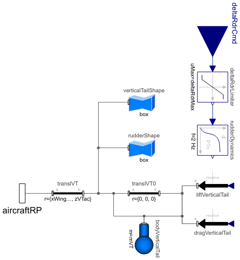
Diagram
Wolfram Language
In[1]:=
SystemModel["Aircraft.Physical.FixedWing.Parts.Surfaces.Components.VerticalTail"]
Out[1]:=
Information
This model calculates the aerodynamic forces due to the vertical tail and rudder, estimates the mass properties of the vertical tail and solves the consequent Newton—Euler equations in the bodyVerticalTail component if the weight estimation is used. If any of the mass properties are known when the weight estimation method is used, their value can be entered directly in the Estimated Mass Properties tab, thus bypassing the equation to estimate their value. Stall due to high sideslip angles is not modeled for the vertical tail.
All other parameters, including the vertical tail and rudder specific parameters, are propagated to this model from the AircraftBase model, and therefore their values should not be changed here but only in the complete aircraft model. Additionally, the variables of the global flight conditions are propagated here from the AircraftBase model inside the flightData record.
All forces in this model act on the aerodynamic center location of the vertical tail. The location of the aerodynamic center along the body x axis is defined by the parameter lVTwingAC, which will assume the location to be at quarter chord at the mean aerodynamic chord (MAC). For calculating the location of the MAC, a simple trapezoidal wing shape is assumed, with the given vertical tail span, root chord, tip chord and sweep angle.
The equations to estimate the aerodynamic center location as well as any other estimated vertical tail parameter can be bypassed by entering the known value in the Vertical Tail group in the Derived Properties parameter tab in the AircraftBase model.
Lift (or Y-force) due to Vertical Tail and Rudder
This section describes how the magnitude and orientation of the lift force are calculated in this model. For the vertical tail, the lift force acts perpendicular to the wind on the body x-y plane.
The parameter for the lift curve slope of the 2D airfoil (ClAlphaVT2D) is used together with other vertical tail properties and the Mach number to derive the lift curve slope for the entire vertical tail (CLα,VT) such that the air compressibility effects are also considered. The complete method to derive CLα,VT is described in detail in section 3.3.2 in Reference [1]. Furthermore, the lift curve slope of the vertical tail with respect to its rudder deflection angle (CLδr,VT) is calculated as the product of CLα,VT and rudder effectiveness parameter, which is derived from the rudder and vertical tail surfaces according to the method presented by Nelson [2].
However, observing the forces and orientation from an entire aircraft perspective, the lift force acting on the body x-y plane on the vertical tail actually is a function of the sideslip angle rather than the angle of attack. Thus, the lift curve slope for the vertical tail with the contribution from the sidewash angle due to the sideslip angle (sigmaBeta) is denoted as CY,β,VT or CyBeta, specifying more clearly the direction of the force and the cause of it. The sigmaBeta is calculated based on a formula presented in section 3.3.4 in Reference [1] and originally presented in USAF DATCOM [6].
Thus, the lift coefficient (or in other words, the Y-force coefficient) of the vertical tail with contribution by the rudder deflection is solved by
![]() ,
,
where βeff,VT is the effective sideslip angle seen by the vertical tail, such that the induced sideslip angle due to yaw rate is considered according to the method presented by Nelson [2].
The dimensionless Y-force coefficient for vertical tail with contribution by the rudder deflection is multiplied by the global dynamic pressure and vertical tail reference area to get the magnitude of the Y-force force acting on the aerodynamic center. The Y-force is oriented such that it is perpendicular to the free stream rather than acting only along the body y axis, as shown in Figure 1.

Figure 1: Orientation of the aerodynamic forces acting on the vertical tail aerodynamic center.
Drag due to Vertical Tail
For solving the parasite drag coefficient (CD,0) of different components in the aircraft, including the vertical tail, the component buildup method presented by Raymer [3] is used, defined as
![]() ,
,
where the form factor (FFVT) and the area (Swet,VT) are functions of the geometry of the vertical tail. The skin friction coefficient (Cf,VT) is a function of the surface roughness height of the vertical tail, Mach number and Reynolds number for the flow over the mean aerodynamic chord of the vertical tail. Thus, the air compressibility effects are included in the drag calculations. The complete derivation of the CD,0,VT can be found in section 3.3.1 in Reference [1].
Lift-induced drag is also considered in the complete drag coefficient for the vertical tail (CD,VT), which reads as
![]() ,
,
where KVT is an empirical factor, and its value is based on the vertical tail geometry and calculated through a method given by Cook [4].
The CD,VT coefficient is multiplied by the global dynamic pressure (q) and the wing reference area (Sref,w) to get the magnitude of the drag force acting on the aerodynamic center of the vertical tail. The drag force is also oriented such that it is always parallel with the free stream, as shown in Figure 1.
Mass Properties
If the weight estimation method is used and no mass properties are entered by the user, the vertical tail mass properties are estimated by using an empirical relationship based on the given parameters describing the vertical tail geometry, its position and the design variables in the AircraftBase model. The vertical tail mass is estimated by a method presented by Nicolai and Carichner [5], and it is further described in section 3.4.3 in Reference [1].
The center of mass location is solved by using an empirical relationship describing its location as fractions of the spanwise and chordwise lengths. The derivation of the vertical tail center of mass location and the equations to solve for its coordinate with respect to the fuselage reference point are described in detail in section 3.5.2 and in Appendix A.1 in Reference [1], respectively.
The vertical tail moments of inertia are estimated by a method presented in USAF DATCOM [6], and it is also converted to be used with SI-Units in Appendix A.2 in Reference [1].
References
[1] Erä-Esko, N. (2022). "Development and Use of System Modeler 6DOF Flight Mechanics Model in Aircraft Conceptual Design."
Available at: modelica://Aircraft/Resources/Documents/EraeEskoThesis.pdf.
[2] Nelson, R. C. (1998). Flight Stability and Automatic Control. 2nd ed. McGraw-Hill.
Available at: http://home.eng.iastate.edu/~shermanp/AERE355/lectures/Flight_Stability_and_Automatic_Control_N.pdf.
[3] Raymer, D. P. (1992). Aircraft Design: A Conceptual Approach, 2nd Ed. American Institute of Aeronautics and Astronautics.
[4] Cook, M. (2012). Flight Dynamics Principles. 3rd ed. Elsevier.
[5] Nicolai, L. M. and G. E.Carichne., (2010). Fundamentals of Aircraft and Airship Design, Volume 1–Aircraft Design.
American Institute of Aeronautics and Astronautics.
[6] Finck, R. D. (1978). USAF (United States Air Force) Stability and Control DATCOM (Data Compendium).
MCDONNELL AIRCRAFT CO ST LOUIS MO
Available at: https://apps.dtic.mil/sti/citations/ADB072483.
Parameters (58)
| weightEst |
Value: Type: Boolean Description: true, if weight estimation method is used for masses, center of mass location and inertia tensor |
|---|---|
| zCMdry |
Value: Type: Length (m) Description: Aircraft center of mass z-coordinate w.r.t. fuselage reference point (with total mass for electric aircraft and gliders, positive z-axis towards ground) |
| MTOMdes |
Value: Type: Mass (kg) Description: Design maximum take-off mass |
| machDes |
Value: Type: Real Description: Design Mach number |
| compMat |
Value: Type: Boolean Description: true, if composite materials are used in structures |
| qMax |
Value: Type: Pressure (Pa) Description: Maximum dynamic pressure |
| nMax |
Value: Type: Real Description: Maximum load factor |
| wFus |
Value: Type: Length (m) Description: Fuselage maximum width |
| hFus |
Value: Type: Length (m) Description: Fuselage maximum height |
| bWing |
Value: Type: Length (m) Description: Main wing span |
| xWingRootLE |
Value: Type: Length (m) Description: Main wing root leading edge x-coordinate w.r.t. fuselage reference point (positive x-axis towards nose) |
| SrefWing |
Value: Type: Area (m²) Description: Main wing reference area |
| xWingAC |
Value: Type: Length (m) Description: Main wing aerodynamic center from wing leading edge at mean chord (positive x-axis towards nose) |
| yWingAC |
Value: Type: Length (m) Description: Main wing aerodynamic center from fuselage centerline (y-coordinate w.r.t. fuselage centerline of mean chord) |
| lambdaWingLE |
Value: Type: Angle (rad) Description: Main wing leading edge sweep angle |
| zHTrootLE |
Value: Type: Length (m) Description: Horizontal tail root leading edge z-coordinate w.r.t. fuselage reference point (positive z-axis towards ground) |
| bVT |
Value: Type: Length (m) Description: Vertical tail span |
| cVTroot |
Value: Type: Length (m) Description: Vertical tail root chord |
| cVTtip |
Value: Type: Length (m) Description: Vertical tail tip chord |
| tVTroot |
Value: Type: Length (m) Description: Vertical tail root thickness |
| zVTroot |
Value: Type: Length (m) Description: Vertical tail root z-coordinate w.r.t fuselage reference point |
| lambdaVT |
Value: Type: Angle (rad) Description: Vertical tail sweep angle at 1/4 chord |
| Srdr |
Value: Type: Area (m²) Description: Rudder area |
| SrefVT |
Value: Type: Area (m²) Description: Vertical tail reference area |
| ARvt |
Value: Type: Real Description: Aspect ratio of vertical tail |
| TRvt |
Value: Type: Real Description: Taper ratio of vertical tail |
| cVTmean |
Value: Type: Length (m) Description: Vertical tail mean chord |
| lVTcm |
Value: Type: Length (m) Description: Vertical tail arm length (from aircraft center of mass to vertical tail 1/4 chord) |
| lVTwingAC |
Value: Type: Length (m) Description: Vertical tail arm length (from wing aerodynamic center to vertical tail aerodynamic center) |
| zVTac |
Value: Type: Length (m) Description: Vertical tail center of pressure z-coordinate w.r.t. fuselage reference point |
| SwetVT |
Value: Type: Area (m²) Description: Vertical tail wetted area |
| lambdaVTle |
Value: Type: Angle (rad) Description: Vertical tail leading edge sweep angle |
| FFvt |
Value: Type: Real Description: Vertical tail form factor |
| sdVT |
Value: Type: Real Description: Fuselage drag factor for vertical tail |
| kdVT |
Value: Type: Real Description: Empirical constant for Oswald efficiency factor for vertical tail |
| tauRdr |
Value: Type: Real Description: Rudder effectiveness parameter |
| sigmaBeta |
Value: Type: Real Description: Change in sidewash due to beta |
| kSkinVT |
Value: Type: Length (m) Description: Vertical tail surface roughness height |
| ClAlphaVT2D |
Value: Type: CurveSlope (rad⁻¹) Description: Change in the section lift coefficient of the vertical tail airfoil (2D) due to alpha |
| deltaRdrMax |
Value: Type: Angle (rad) Description: Maximum rudder deflection |
| CADshapes |
Value: Type: Boolean Description: true, if external CAD files are used for animation |
| rho0 |
Value: Type: Density (kg/m³) Description: Air density at sea-level |
| a0 |
Value: Type: Velocity (m/s) Description: Speed of sound at sea-level |
| mVT |
Value: if machDes < 0.4 then if compMat then 0.75 * (98.5 * (MTOMdes * 2.2046 * nMax * 1.5 / 10 ^ 5) ^ 0.87 * (SrefVT * 10.764 / 100) ^ 1.2 * (bVT * 3.281 / (tVTroot * 39.37)) ^ 0.5) / 2.2046 else 98.5 * (MTOMdes * 2.2046 * nMax * 1.5 / 10 ^ 5) ^ 0.87 * (SrefVT * 10.764 / 100) ^ 1.2 * (bVT * 3.281 / (tVTroot * 39.37)) ^ 0.5 / 2.2046 else if compMat then 0.75 * 0.19 * ((1 + min(zHTrootLE - zVTroot, 0) / (-bVT)) ^ 0.5 * (MTOMdes * 2.2046 * nMax * 1.5) ^ 0.363 * (SrefVT * 10.764) ^ 1.089 * (sqrt(2 * qMax / rho0) / a0) ^ 0.601 * (lVTwingAC * 3.281) ^ (-0.726) * (1 + Srdr / SrefVT) ^ 0.217 * ARvt ^ 0.337 * (1 + TRvt) ^ 0.363 * cos(lambdaVT) ^ (-0.484)) ^ 1.014 / 2.2046 else 0.19 * ((1 + min(zHTrootLE - zVTroot, 0) / (-bVT)) ^ 0.5 * (MTOMdes * 2.2046 * nMax * 1.5) ^ 0.363 * (SrefVT * 10.764) ^ 1.089 * (sqrt(2 * qMax / rho0) / a0) ^ 0.601 * (lVTwingAC * 3.281) ^ (-0.726) * (1 + Srdr / SrefVT) ^ 0.217 * ARvt ^ 0.337 * (1 + TRvt) ^ 0.363 * cos(lambdaVT) ^ (-0.484)) ^ 1.014 / 2.2046 Type: Mass (kg) Description: Vertical tail mass |
| rCMvt |
Value: {xWingRootLE - tan(lambdaWingLE) * (yWingAC - wFus / 2) + xWingAC - lVTwingAC, 0, zVTac} + {xVTcm, 0, bVT * (1 + 2 * TRvt) / (3 + 3 * TRvt) + zVTcm} Type: Length[3] (m) Description: Vertical tail center of mass coordinates w.r.t. fuselage reference point |
| IxxVT |
Value: 0.000293 * (mVT * 2.205 * (bVT * 39.37) ^ 2 * k1VT) / 18 * (1 + 2 * cVTroot * 39.37 * cVTtip * 39.37 / (cVTroot * 39.37 + cVTtip * 39.37) ^ 2) Type: MomentOfInertia (kg⋅m²) Description: Vertical tail roll moment of inertia |
| IyyVT |
Value: IxxVT + IzzVT Type: MomentOfInertia (kg⋅m²) Description: Vertical tail pitch moment of inertia |
| IzzVT |
Value: 0.000293 * 0.771 * (i0VT - wvtxVT ^ 2 / (mVT * 2.205)) Type: MomentOfInertia (kg⋅m²) Description: Vertical tail yaw moment of inertia |
| xVTcm |
Value: 0.25 * cVTmean + tan(lambdaVTle) * bVT * (1 + 2 * TRvt) / (3 + 3 * TRvt) - tan(lambdaVTle) * abs(zVTcm) - 0.42 * cVTcm Type: Length (m) Description: Vertical tail center of mass x-coordinate w.r.t. Vertical tail aerodynamic center (positive x-axis towards nose) |
| zVTcm |
Value: (min(zHTrootLE - zVTroot, 0) / (-bVT) * (0.55 - 0.38) + 0.38) * (-bVT) Type: Length (m) Description: Vertical tail center of mass z-coordinate w.r.t. its root at fuselage (positive z-axis towards ground) |
| cVTcm |
Value: (cVTtip - cVTroot) / bVT * abs(zVTcm) + cVTroot Type: Length (m) Description: Chord length at vertical tail center of mass |
| caVT |
Value: min({bVT * 2 * tan(lambdaVTle) / 2 * 39.37, cVTtip * 39.37 + bVT * 2 * tan(lambdaVTle) / 2 * 39.37, cVTroot * 39.37}) Type: Real Description: Factor for calculating vertical tail moment of inertias |
| cbVT |
Value: sum({bVT * 2 * tan(lambdaVTle) / 2 * 39.37, cVTtip * 39.37 + bVT * 2 * tan(lambdaVTle) / 2 * 39.37, cVTroot * 39.37}) - caVT - ccVT Type: Real Description: Factor for calculating vertical tail moment of inertias |
| ccVT |
Value: max({bVT * 2 * tan(lambdaVTle) / 2 * 39.37, cVTtip * 39.37 + bVT * 2 * tan(lambdaVTle) / 2 * 39.37, cVTroot * 39.37}) Type: Real Description: Factor for calculating vertical tail moment of inertias |
| k1VT |
Value: -0.988158 + 2.20444 * (abs(zVTcm) / (bVT / 3 * (cVTroot + 2 * cVTtip) / (cVTroot + cVTtip))) ^ 1.1 Type: Real Description: Factor for calculating vertical tail moment of inertias |
| rhoiVT |
Value: mVT * 2 * 2.205 / (-caVT + cbVT + ccVT) Type: Real Description: Factor for calculating vertical tail moment of inertias |
| wvtxVT |
Value: rhoiVT / 6 * (-caVT ^ 2 + cbVT ^ 2 + ccVT * cbVT + ccVT ^ 2) Type: Real Description: Factor for calculating vertical tail moment of inertias |
| i0VT |
Value: rhoiVT / 12 * (-caVT ^ 3 + cbVT ^ 3 + ccVT ^ 2 * cbVT + ccVT * cbVT ^ 2 + ccVT ^ 3) Type: Real Description: Factor for calculating vertical tail moment of inertias |
Inputs (1)
| flightData |
Type: FlightData Description: Global flight data variables |
|---|
Connectors (2)
Components (10)
| flightData |
Type: FlightData Description: Global flight data variables |
|
|---|---|---|
| liftVerticalTail |
Type: WorldForce Description: Vertical tail and rudder lift force |
|
| verticalTailShape |
Type: FixedShape Description: Visualization of vertical tail |
|
| rudderShape |
Type: FixedShape Description: Visualization of rudder |
|
| rudderDynamics |
Type: CriticalDamping Description: Simplified model of the rudder actuator dynamics |
|
| deltaRdrLimiter |
Type: Limiter Description: Limits rudder deflection to its assigned limits |
|
| dragVerticalTail |
Type: WorldForce Description: Vertical tail drag force |
|
| translVT |
Type: FixedTranslation Description: Position of vertical tail aerodynamic center w.r.t fuselage reference point |
|
| bodyVerticalTail |
Type: Body Description: Mass and inertia of vertical tail |
|
| translVT0 |
Type: FixedTranslation Description: Translation to bypass bodyVerticalTail if no weight estimation is used |
Used in Components (1)
|
Aircraft.Physical.FixedWing.Parts.Surfaces Model of system of surfaces in conventional wing configuration |