WOLFRAM SYSTEM MODELER
WingBodyContribution from wing-body combination to aerodynamic forces |
|
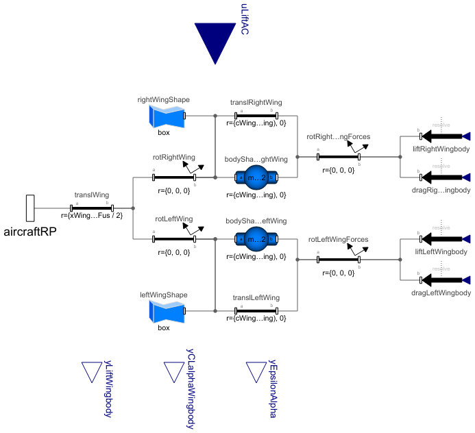
Diagram
Wolfram Language
In[1]:=
SystemModel["Aircraft.Physical.FixedWing.Parts.Surfaces.Components.WingBody"]
Out[1]:=
Information
This model calculates the aerodynamic forces due to the wing-body (combination of fuselage and main wing), estimates the mass properties of the main wing and solves the consequent Newton—Euler equations in the bodyShapeLeftWing and bodyShapeRightWing components if the weight estimation is used. If any of the mass properties are known when the weight estimation method is used, their value can be entered directly in the Estimated Mass Properties tab, thus bypassing the equation to estimate their value.
All other parameters, including the wing-body specific parameters, are propagated to this model from the AircraftBase model, and therefore their values should not be changed here but only in the complete aircraft model. Additionally, the variables of the global flight conditions are propagated here from the AircraftBase model inside the flightData record.
All forces in this model act on the aerodynamic center locations on both sides of the main wing, including the aerodynamic forces due to the fuselage. The location of the aerodynamic center is defined by the parameters xWingAC and yWingAC, which will assume the location to be at quarter chord at the mean aerodynamic chord (MAC). For calculating the location of the MAC, a simple trapezoidal wing shape is assumed, with the given wing span, root chord, tip chord and sweep angle. On the body z axis, the aerodynamic center location is solved from the given z coordinate for main wing root chord leading edge (zWingRootLE), dihedral angle (gammaWing) and yWingAC.
The equations to estimate the aerodynamic center location as well as any other estimated main wing parameter can be bypassed by entering the known value in the Main Wing group in the Derived Properties parameter tab in the AircraftBase model.
The contribution to the aerodynamic forces by ailerons is not included in this model but in its dedicated Ailerons model.
Lift due to Wing-Body
This section describes how the magnitude and orientation of the lift force are calculated in this model.
The parameter for the lift curve slope of the 2D airfoil (ClAlphaWing2D) is used together with other main wing properties and the Mach number to derive the lift curve slope for the entire main wing (CLα,w) such that the air compressibility effects are also considered. Furthermore, an empirical relationship is used to derive the lift curve slope of the wing-body combination (CLα,wb) from the main wing lift curve slope and the properties of the fuselage. Thus, the lift coefficient of the wing-body is solved by
![]() ,
,
where αeff,w is the effective angle of attack seen by the main wing, such that the contribution of the wing incidence angle, wing zero-lift angle and the induced angle of attack due to wing dihedral in sideslip (Δα) are considered. The Δα is estimated here as the product of the sideslip angle (β) and wing dihedral angle (Γ), as given by Nelson [1]. Due to the differential contribution by Δα to the αeff,w value, the lift coefficient of the wing-body have different values on different sides of the wing (if Γ ≠ 0). All steps to derive the wing-body lift coefficient are described in detail in section 3.3.2 in Reference [2].
The dimensionless lift coefficient for wing-body is multiplied by the global dynamic pressure and half of the wing reference area to get the magnitude of the lift force acting on the aerodynamic center on one side of the main wing. The lift force is oriented such that it is perpendicular to the free stream. Additionally, components along the body y axis are added to the lift force to account for the wing dihedral angle, as shown in Figure 1. Thus, the resultant lift force is actually greater than Lwb but the components acting on the body x-z plane still always equals to Lwb.

Figure 1: Orientation of the aerodynamic forces acting on the main wing aerodynamic center.
In addition to the ordinary lift force, the induced lift forces acting along the body z axis are also modeled and added to the forces acting on the main wing aerodynamic centers. They are the induced z force due to yaw rate and the induced z force due to roll rate, and their values are calculated as presented in Nelson [1].
Drag Due to Wing and Fuselage
For solving the parasite drag coefficient (CD,0) of different components (c) in the aircraft, including the main wing and fuselage, the component buildup method presented by Raymer [3] is used, defined as
![]() ,
,
where the form factor (FFc) and the area (Swet,c) are functions of the geometry of the main wing and fuselage. The skin friction coefficient (Cf,c) is a function of the surface roughness height of main wing and fuselage, Mach number and Reynolds number for the flow over the mean aerodynamic chord of the main wing and over the fuselage length. Thus, the air compressibility effects are included in the drag calculations. The complete derivation of the CD,0,c can be found in section 3.3.1 in Reference [2].
For both the fuselage and the main wing, lift-induced drag is also considered in the complete drag coefficient (CD,w and CD,fus). For the main wing, the complete drag coefficient reads as
![]() ,
,
where Kw is an empirical factor, and its value is based on the wing geometry and calculated through a method given by Cook [4]. For the fuselage, the lift-induced drag is calculated as a function of the maximum fuselage drag coefficient that is achieved at α = 90° and the current angle of attack. The complete derivation of the equations to solve for CD,fus is described in section 3.3.1 in Reference [2].
The CD,w coefficient is multiplied by the global dynamic pressure (q) and half of the wing reference area (Sref,w / 2) to get the magnitude of the drag force acting on the aerodynamic center on one side of the main wing. To solve the drag force due to fuselage, the CD,fus coefficient is multiplied by q and Sref,w. The magnitude of the drag force due to the wing-body acting on the aerodynamic center on either side of the main wing is
![]() .
.
This drag force might be different on each side of the main wing due to the contribution by the main wing lift-induced drag, as the lift can differ between the different sides of the main wing. The drag force is also oriented such that it always is parallel with the free stream, as shown in Figure 1.
In addition to the ordinary drag force, the induced drag force acting along the body x axis due to roll rate is also modeled and added to the forces acting on the main wing aerodynamic centers. Its value is calculated as presented by Nelson [1].
Stall
Stall, which occurs at high angles of attack due to flow separation on the wing upper surface, is modeled for the wing-body up to αeff = 90°, but not for large negative angles of attack.
The wing-body lift coefficient (CL,wb) follows the linear lift curve slope, i.e. the CLα,wb, until the vicinity of achieving the maximum value for main wing lift coefficient (CL,max,w), after which it starts following different quadratic equations. The quadratic equations are calculated based on the constraints shown in Figure 2 to generate a generic stall model for a wing. The constraints also include that the function for CL,wb needs to be differentiable everywhere.
The parameter for CL,max,w, which is derived from the maximum lift coefficient of the 2D airfoil (ClMaxWing2D), is used together with CLα,wb to define the constraints for the different quadratic equations, which are highlighted with different colors in Figure 2.

Figure 2: Model for wing lift coefficient in stall. [2]
The main wing drag coefficient (CD,w) follows the equation defined in the previous section until the CL,w coefficient achieves CL,max,w, after which it starts following a sine curve toward the maximum drag coefficient value (CD,max,w) at αeff = 90°, as shown in Figure 3. The value of the CD,max,w coefficient is calculated based on the drag coefficient of a flat plate, which has same aspect ratio as the main wing and is perpendicular to the wind. Additionally, in order to make the function for CD,w differentiable where it transits into the sine curve, a cubic function is fitted between 1° before and 1° after the intersection.

Figure 3: Model for wing drag coefficient in stall. [2]
Further explanation about stall and how it is modeled in the library can be found in section 3.3.3 in Reference [2].
Mass Properties
If the weight estimation method is used and no mass properties are entered by the user, the main wing mass properties are estimated by using an empirical relationship based on the given parameters describing the wing geometry and the design variables in the AircraftBase model. The main wing mass is estimated by a method presented by Nicolai and Carichner [5], and it is further described in section 3.4.2 in Reference [2].
The center of mass location is solved individually for both sides of the main wing by using an empirical relationship describing their locations as fractions of the spanwise and chordwise lengths such that the rotations around the wing incidence and dihedral angles are also considered. The derivation of the main wing center of mass locations and the equations to solve for their coordinates with respect to the fuselage reference point are described in detail in section 3.5.2 and in Appendix A.1 in Reference [2], respectively.
The main wing moments of inertia are estimated by a method presented in USAF DATCOM [6], and it is also converted to be used with SI units in Appendix A.2 in Reference [2].
References
[1] Nelson, R. C. (1998). Flight Stability and Automatic Control. 2nd ed. McGraw-Hill.
Available at: http://home.eng.iastate.edu/~shermanp/AERE355/lectures/Flight_Stability_and_Automatic_Control_N.pdf.
[2] Erä-Esko, N. (2022). "Development and Use of System Modeler 6DOF Flight Mechanics Model in Aircraft Conceptual Design."
Available at: modelica://Aircraft/Resources/Documents/EraeEskoThesis.pdf.
[3] Raymer, D. P. (1992). Aircraft Design: A Conceptual Approach, 2nd Ed. American Institute of Aeronautics and Astronautics.
[4] Cook, M. (2012). Flight Dynamics Principles. 3rd ed. Elsevier.
[5] Nicolai, L. M. and G. E.Carichne., (2010). Fundamentals of Aircraft and Airship Design, Volume 1–Aircraft Design.
American Institute of Aeronautics and Astronautics.
[6] Finck, R. D. (1978). USAF (United States Air Force) Stability and Control DATCOM (Data Compendium).
MCDONNELL AIRCRAFT CO ST LOUIS MO
Available at: https://apps.dtic.mil/sti/citations/ADB072483.
Parameters (57)
| weightEst |
Value: Type: Boolean Description: true, if weight estimation method is used for masses, center of mass location and inertia tensor |
|---|---|
| xCMdry |
Value: Type: Length (m) Description: Aircraft center of mass x-coordinate w.r.t. fuselage reference point (with total mass for electric aircraft and gliders, positive x-axis towards nose) |
| MTOMdes |
Value: Type: Mass (kg) Description: Design maximum take-off mass |
| machDes |
Value: Type: Real Description: Design Mach number |
| compMat |
Value: Type: Boolean Description: true, if composite materials are used in structures |
| qMax |
Value: Type: Pressure (Pa) Description: Maximum dynamic pressure |
| nMax |
Value: Type: Real Description: Maximum load factor |
| lFus |
Value: Type: Length (m) Description: Fuselage length |
| wFus |
Value: Type: Length (m) Description: Fuselage maximum width |
| SwetFus |
Value: Type: Area (m²) Description: Fuselage wetted area |
| FFfus |
Value: Type: Real Description: Fuselage form factor |
| bWing |
Value: Type: Length (m) Description: Main wing span |
| cWingRoot |
Value: Type: Length (m) Description: Main wing root chord (where wing intersects with fuselage) |
| cWingTip |
Value: Type: Length (m) Description: Main wing tip chord |
| tWingRoot |
Value: Type: Length (m) Description: Main wing root thickness |
| xWingRootLE |
Value: Type: Length (m) Description: Main wing root leading edge x-coordinate w.r.t. fuselage reference point (positive x-axis towards nose) |
| zWingRootLE |
Value: Type: Length (m) Description: Main wing root leading edge z-coordinate w.r.t. fuselage reference point (positive z-axis towards ground) |
| lambdaWing |
Value: Type: Angle (rad) Description: Main wing sweep angle at 1/4 chord |
| gammaWing |
Value: Type: Angle (rad) Description: Main wing dihedral angle |
| iWing |
Value: Type: Angle (rad) Description: Main wing incidence angle |
| SrefWing |
Value: Type: Area (m²) Description: Main wing reference area |
| ARwing |
Value: Type: Real Description: Main wing aspect ratio |
| TRwing |
Value: Type: Real Description: Main wing taper ratio |
| cWingMean |
Value: Type: Length (m) Description: Main wing mean chord length |
| xWingAC |
Value: Type: Length (m) Description: Main wing aerodynamic center from wing leading edge at mean chord (positive x-axis towards nose) |
| yWingAC |
Value: Type: Length (m) Description: Main wing aerodynamic center from fuselage centerline (y-coordinate w.r.t. fuselage centerline of mean chord) |
| SwetWing |
Value: Type: Area (m²) Description: Main wing wetted area |
| lambdaWingLE |
Value: Type: Angle (rad) Description: Main wing leading edge sweep angle |
| lambdaWingHC |
Value: Type: Angle (rad) Description: Main wing half-chord sweep angle |
| FFwing |
Value: Type: Real Description: Main wing form factor |
| sdWing |
Value: Type: Real Description: Fuselage drag factor for main wing |
| kdWing |
Value: Type: Real Description: Empirical constant for Oswald efficiency factor for main wing |
| kSkinFus |
Value: Type: Length (m) Description: Fuselage surface roughness height |
| CDmaxFus |
Value: Type: Real Description: Maximum drag coefficient of the fuselage |
| kSkinWing |
Value: Type: Length (m) Description: Main Wing surface roughness height |
| ClAlphaWing2D |
Value: Type: CurveSlope (rad⁻¹) Description: Change in the section lift coefficient of the main wing airfoil (2D) due to alpha |
| alpha0Wing2D |
Value: Type: Angle (rad) Description: Zero-lift angle of attack of the main wing airfoil (2D) |
| CLmaxWing3D |
Value: Type: Real Description: Maximum lift coefficient of the main wing (3D) |
| CDmaxWing3D |
Value: Type: Real Description: Maximum drag coefficient of the main wing (3D) |
| CADshapes |
Value: Type: Boolean Description: true, if external CAD files are used for animation |
| rho0 |
Value: Type: Density (kg/m³) Description: Air density at sea-level |
| a0 |
Value: Type: Velocity (m/s) Description: Speed of sound at sea-level |
| mWing |
Value: if machDes < 0.4 then if compMat then 0.8 * 96.948 * ((MTOMdes * 2.2046 * nMax * 1.5 / 10 ^ 5) ^ 0.65 * (ARwing / cos(lambdaWing)) ^ 0.57 * (SrefWing * 10.764 / 100) ^ 0.61 * ((1 + TRwing) / (2 * (tWingRoot / cWingRoot))) ^ 0.36 * sqrt(1 + sqrt(2 * qMax / rho0) * 1.9438 / 500)) ^ 0.993 / 2.2046 else 96.948 * ((MTOMdes * 2.2046 * nMax * 1.5 / 10 ^ 5) ^ 0.65 * (ARwing / cos(lambdaWing)) ^ 0.57 * (SrefWing * 10.764 / 100) ^ 0.61 * ((1 + TRwing) / (2 * (tWingRoot / cWingRoot))) ^ 0.36 * sqrt(1 + sqrt(2 * qMax / rho0) * 1.9438 / 500)) ^ 0.993 / 2.2046 else if compMat then 0.8 * 0.00428 * (SrefWing * 10.764) ^ 0.48 * (ARwing * (sqrt(2 * qMax / rho0) / a0) ^ 0.43 * (MTOMdes * 2.2046 * nMax * 1.5) ^ 0.84 * TRwing ^ 0.14) / ((100 * (tWingRoot / cWingRoot)) ^ 0.76 * cos(lambdaWingHC) ^ 1.54) / 2.2046 else 0.00428 * (SrefWing * 10.764) ^ 0.48 * (ARwing * (sqrt(2 * qMax / rho0) / a0) ^ 0.43 * (MTOMdes * 2.2046 * nMax * 1.5) ^ 0.84 * TRwing ^ 0.14) / ((100 * (tWingRoot / cWingRoot)) ^ 0.76 * cos(lambdaWingHC) ^ 1.54) / 2.2046 Type: Mass (kg) Description: Main wing mass |
| rCMwingRight |
Value: {xWingRootLE + tan(lambdaWingLE) * wFus / 2 - cWingRoot / 4, 0, zWingRootLE - tan(gammaWing) * wFus / 2} + {xWingCM, yWingCM, -tan(gammaWing) * yWingCM} Type: Length[3] (m) Description: Right wing center of mass coordinates w.r.t. fuselage reference point |
| rCMwingLeft |
Value: {xWingRootLE + tan(lambdaWingLE) * wFus / 2 - cWingRoot / 4, 0, zWingRootLE - tan(gammaWing) * wFus / 2} + {xWingCM, -yWingCM, -tan(gammaWing) * yWingCM} Type: Length[3] (m) Description: Left wing center of mass coordinates w.r.t. fuselage reference point |
| IyyWing |
Value: 0.000293 * 0.703 * (i0Wing - wvxWing ^ 2 / (mWing * 2.205 / 2)) Type: MomentOfInertia (kg⋅m²) Description: (Half) wing pitch moment of inertia |
| IxxWing |
Value: 0.000293 * (mWing / 2 * 2.205 * (bWing / 2 * 39.37) ^ 2 * k1Wing) / 18 * (1 + 2 * cWingRoot * 39.37 * cWingTip * 39.37 / (cWingRoot * 39.37 + cWingTip * 39.37) ^ 2) Type: MomentOfInertia (kg⋅m²) Description: (Half) wing roll moment of inertia |
| IzzWing |
Value: IxxWing + IyyWing Type: MomentOfInertia (kg⋅m²) Description: (Half) wing yaw moment of inertia |
| xWingCM |
Value: if lambdaWing < 0 or lambdaWing > 0 then cWingRoot / 4 - tan(lambdaWingLE) * (0.35 * bWing / 2 - wFus / 2) - 0.5 * ((cWingTip - cWingRoot) / (bWing / 2 - wFus / 2) * (0.35 * bWing / 2 - wFus / 2) + cWingRoot) else cWingRoot / 4 - tan(lambdaWingLE) * (0.4 * bWing / 2 - wFus / 2) - 0.4 * ((cWingTip - cWingRoot) / (bWing / 2 - wFus / 2) * (0.4 * bWing / 2 - wFus / 2) + cWingRoot) Type: Length (m) Description: Main wing center of mass x-coordinate w.r.t. wing root quarter chord (inside fuselage) |
| yWingCM |
Value: if lambdaWing < 0 or lambdaWing > 0 then 0.35 * bWing / 2 else 0.4 * bWing / 2 Type: Length (m) Description: (Half) wing center of mass y-coordinate w.r.t. fuselage centerline |
| caWing |
Value: min({bWing * tan(lambdaWingLE) / 2 * 39.37, cWingTip * 39.37 + bWing * tan(lambdaWingLE) / 2 * 39.37, cWingRoot * 39.37}) Type: Real Description: Factor for calculating wing moment of inertias |
| cbWing |
Value: sum({bWing * tan(lambdaWingLE) / 2 * 39.37, cWingTip * 39.37 + bWing * tan(lambdaWingLE) / 2 * 39.37, cWingRoot * 39.37}) - caWing - ccWing Type: Real Description: Factor for calculating wing moment of inertias |
| ccWing |
Value: max({bWing * tan(lambdaWingLE) / 2 * 39.37, cWingTip * 39.37 + bWing * tan(lambdaWingLE) / 2 * 39.37, cWingRoot * 39.37}) Type: Real Description: Factor for calculating wing moment of inertias |
| k1Wing |
Value: -0.988158 + 2.20444 * (yWingCM / (bWing / 2 / 3 * (cWingRoot + 2 * cWingTip) / (cWingRoot + cWingTip))) ^ 1.1 Type: Real Description: Factor for calculating wing moment of inertias |
| rhoiWing |
Value: mWing * 2.205 / (-caWing + cbWing + ccWing) Type: Real Description: Factor for calculating wing moment of inertias |
| wvxWing |
Value: rhoiWing / 6 * (-caWing ^ 2 + cbWing ^ 2 + ccWing * cbWing + ccWing ^ 2) Type: Real Description: Factor for calculating wing moment of inertias |
| i0Wing |
Value: rhoiWing / 12 * (-caWing ^ 3 + cbWing ^ 3 + ccWing ^ 2 * cbWing + ccWing * cbWing ^ 2 + ccWing ^ 3) Type: Real Description: Factor for calculating wing moment of inertias |
Inputs (1)
| flightData |
Type: FlightData Description: Global flight data variables |
|---|
Connectors (5)
| aircraftRP |
Type: Frame_b Description: Connector to aircraft reference point |
|
|---|---|---|
| yLiftWingbody |
Type: RealOutput Description: Lift force due to wing-body |
|
| uLiftAC |
Type: RealInput Description: Total lift force |
|
| yEpsilonAlpha |
Type: RealOutput Description: Change in downwash due to alpha |
|
| yCLalphaWingbody |
Type: RealOutput Description: Change in the lift coefficient of the wing-body due to alpha |
Components (16)
| flightData |
Type: FlightData Description: Global flight data variables |
|
|---|---|---|
| liftRightWingbody |
Type: WorldForce Description: Right wing-body lift force |
|
| liftLeftWingbody |
Type: WorldForce Description: Left wing-body lift force |
|
| dragRightWingbody |
Type: WorldForce Description: Right wing-body drag force |
|
| dragLeftWingbody |
Type: WorldForce Description: Left wing-body drag force |
|
| bodyShapeRightWing |
Type: BodyShape Description: Mass and inertia tensor of right wing |
|
| translWing |
Type: FixedTranslation Description: Position of the main wing root quarter chord (inside fuselage) w.r.t fuselage reference point |
|
| rotRightWing |
Type: FixedRotation Description: Rotation of right wing around dihedral and wing incidence angle |
|
| rotLeftWing |
Type: FixedRotation Description: Rotation of left wing around dihedral and wing incidence angle |
|
| bodyShapeLeftWing |
Type: BodyShape Description: Mass and inertia tensor of left wing |
|
| rotRightWingForces |
Type: FixedRotation Description: Rotation of aerodynamic forces acting on right wing around dihedral and wing incidence angle |
|
| rotLeftWingForces |
Type: FixedRotation Description: Rotation of aerodynamic forces acting on left wing around dihedral and wing incidence angle |
|
| rightWingShape |
Type: FixedShape Description: Visualization on right wing |
|
| leftWingShape |
Type: FixedShape Description: Visualization on left wing |
|
| translRightWing |
Type: FixedTranslation Description: Translation from the main wing root quarter chord (inside fuselage) to right wing aerodynamic center |
|
| translLeftWing |
Type: FixedTranslation Description: Translation from the main wing root quarter chord (inside fuselage) to left wing aerodynamic center |
Used in Components (1)
|
Aircraft.Physical.FixedWing.Parts.Surfaces Model of system of surfaces in conventional wing configuration |