WOLFRAM SYSTEM MODELER
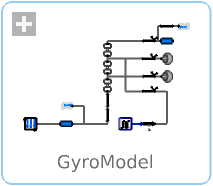
GyroModelExample of how gyroscopic precession works on a simple gyro. |
|
Diagram
Wolfram Language
In[1]:=
SystemModel["EducationExamples.Physics.GyroscopicPrecession.GyroModel"]
Out[1]:=
Information
This model studies how the torque applied to a rotating object may induce gyroscopic precession.
Gyro Model
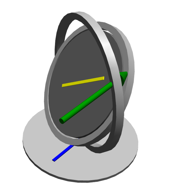
The gyro in this model consists of a mount on which a rotor is placed in a system of two outer rings. This system makes it possible for the rotor to rotate in all three spatial dimensions (see graphic below). The rotor is given an initial angular velocity, and after a little while an external force acts on the inner ring, inducing a phenomenon called gyroscopic precession. An easy way of visualizing what is going on is to just add a 90 degree delay of the force being applied; a force being applied to the "3 o'clock" position acts as if it is being applied at the "12 o'clock" position (provided the rotor is spinning counterclockwise).
Simulation
By simulating the model, you can try different values of the parameters and see how the gyro behaves. One of the most interesting parameters is the degreeOfForce, which will put the force on the inner ring at the degree specified, where 0 degrees is "3 o'clock", 90 degrees is "12 o'clock", etc. Try different values and check for yourself that the force always gets delayed by 90 degrees. Also try different values of the strength of the force (here called forceMagnitude) and the angular speed (here called spin) of the rotor and see how this affects the motion.
To simulate the model and see the generated 3D animation, follow the steps below:
Click the Simulate button: 
Click the Animation button: 
Use your mouse or trackpad to drag the animation to a good angle and zoom in with your scroll wheel or by using the trackpad. Then click the Play button: 
If you would like to examine other things like angles and speeds during the simulation, you can plot these in the Simulation Center. Double click the RevolutionAngles plot in the Stored Plots section to see a plot of the angle of the inner ring.
Gyroscopic Precession
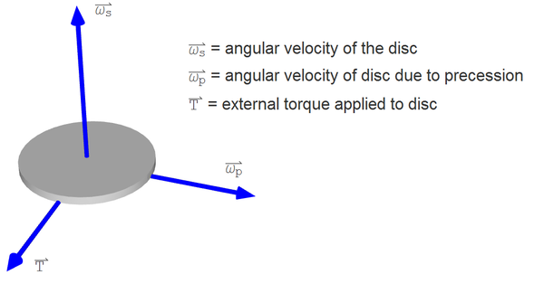
Earlier the gyroscopic precession was described as a 90 degree delay of a force applied to a rotating body. While this is perfectly true, there is a more mathematical way of describing it. There are three physical quantities involved in gyroscopic precession: T, ωp, ωs, where T is the applied torque, ωp is the angular velocity due to precession, and ωs is the angular velocity of the rotor. These three make up a right-handed system in this order. This means, for example, that if the rotor spins around the x axis and torque is applied around the y axis, the gyro starts precessing around the z axis. The graphic below illustrates a rotor and the three rotational quantities. The vectors denote the direction of the rotational axes.
Parameters (3)
| spin |
Value: 500 Type: AngularVelocity (rad/s) Description: Angular velocity of inner rotor |
|---|---|
| forceMagnitude |
Value: 0.3 Type: Force (N) Description: Magnitude of applied force |
| degreeOfForce |
Value: 45 Type: Angle_deg (°) Description: Angle of applied force |
Components (19)
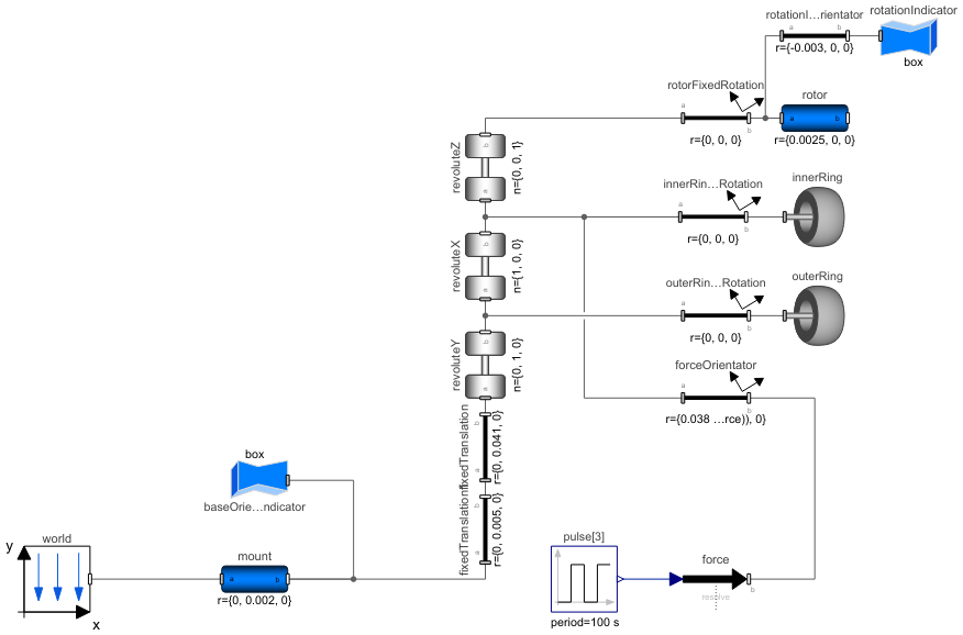
| world |
Type: World Description: world component |
|
|---|---|---|
| mount |
Type: BodyCylinder Description: mount of the gyro |
|
| outerRing |
Type: VoluminousWheel Description: outer ring of the gyro |
|
| fixedTranslation |
Type: FixedTranslation Description: distance from the outer ring to the center of the gyro |
|
| outerRinFixedgRotation |
Type: FixedRotation Description: fixed rotation to line up the outer ring initially |
|
| innerRing |
Type: VoluminousWheel Description: inner ring of the gyro |
|
| innerRingFixedRotation |
Type: FixedRotation Description: fixed rotation to line up the inner ring initially |
|
| fixedTranslation1 |
Type: FixedTranslation Description: distance from the mount to the outer ring |
|
| rotor |
Type: BodyCylinder Description: the rotor of the gyro |
|
| rotorFixedRotation |
Type: FixedRotation Description: fixed rotation to line up the rotor initially |
|
| revoluteX |
Type: Revolute Description: revolution around the x-axis |
|
| revoluteZ |
Type: Revolute Description: revolution around the Z-axis |
|
| revoluteY |
Type: Revolute Description: revolution around the Y-axis |
|
| rotationIndicator |
Type: FixedShape Description: indicator of the orientation of the rotor |
|
| rotationIndicatorOrientator |
Type: FixedTranslation Description: placement for the indicator of the rotor orientation |
|
| force |
Type: WorldForce Description: external force |
|
| pulse |
Type: Pulse[3] Description: signal to external force |
|
| baseOrientationIndicator |
Type: FixedShape Description: indicator of the orientation of the mount |
|
| forceOrientator |
Type: FixedRotation Description: displacement showing where to put the external force |