WOLFRAM SYSTEM MODELER
BevelGear1DDemonstrates the usage of a BevelGear1D model and how to calculate the power of such an element |
|
Diagram
Wolfram Language
In[1]:=
SystemModel["Modelica.Mechanics.MultiBody.Examples.Rotational3DEffects.BevelGear1D"]
Out[1]:=
Information
This information is part of the Modelica Standard Library maintained by the Modelica Association.
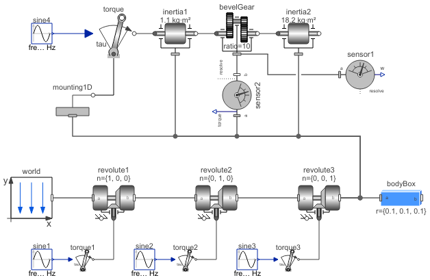
This model consists of a drive train with two inertias that are coupled by a bevel gear (with 90 degree angle between the two gear flanges). This drive train is mounted on a body that is rotated along three axes. The drive train is modeled with 1D rotational elements that take into account 3D effects.
The bevelGear component consists of two rotational flanges (for the gear flanges) and one 3D frame (for the support/mounting). Since the bevelGear does not store energy, the power balance must hold (the total sum of inflowing and outflowing energy must be zero). One has to be careful, when computing the energy flow of hybrid 1D/3D component: The angular velocities of rotational flanges are with respect to the support frame (so the moving body on which the drive train is mounted). Therefore, when computing the energy flow, first the absolute angular velocities of the flanges have to be calculated. In this example model, this is performed in the following way (na and nb are the axes of rotations of the gear flanges, and ws is the angular velocity of the support frame):
  import Modelica.Mechanics.MultiBody.Frames;

  SI.Power           bevelGearPower;
  SI.AngularVelocity ws[3] = Frames.angularVelocity2(bevelGear.frame_a.R);
equation
  bevelGearPower = (ws + der(bevelGear.flange_a.phi)*na)*bevelGear.flange_a.tau*na +
                   (ws + der(bevelGear.flange_b.phi)*nb)*bevelGear.flange_b.tau*nb +
                   ws*bevelGear.frame_a.t;
The total energy flow bevelGearPower must be zero. If a relative tolerance of 1e-4 is used for simulation, bevelGearPower is in the order of 1e-8 (and smaller for a smaller relative tolerance).
Parameters (2)
Components (19)
| world |
Type: World Description: World coordinate system + gravity field + default animation definition |
|
|---|---|---|
| inertia1 |
Type: Rotor1D Description: 1D inertia attachable on 3-dim. bodies (3D dynamic effects are taken into account if world.driveTrainMechanics3D=true) |
|
| inertia2 |
Type: Rotor1D Description: 1D inertia attachable on 3-dim. bodies (3D dynamic effects are taken into account if world.driveTrainMechanics3D=true) |
|
| bevelGear |
Type: BevelGear1D Description: 1D gearbox with arbitrary shaft directions and 3-dim. bearing frame (3D dynamic effects are taken into account provided world.driveTrainMechanics3D=true) |
|
| revolute1 |
Type: Revolute Description: Revolute joint (1 rotational degree-of-freedom, 2 potential states, optional axis flange) |
|
| revolute2 |
Type: Revolute Description: Revolute joint (1 rotational degree-of-freedom, 2 potential states, optional axis flange) |
|
| revolute3 |
Type: Revolute Description: Revolute joint (1 rotational degree-of-freedom, 2 potential states, optional axis flange) |
|
| torque1 |
Type: Torque Description: Input signal acting as external torque on a flange |
|
| torque2 |
Type: Torque Description: Input signal acting as external torque on a flange |
|
| torque3 |
Type: Torque Description: Input signal acting as external torque on a flange |
|
| sine1 |
Type: Sine Description: Generate sine signal |
|
| sine2 |
Type: Sine Description: Generate sine signal |
|
| sine3 |
Type: Sine Description: Generate sine signal |
|
| mounting1D |
Type: Mounting1D Description: Propagate 1-dim. support torque to 3-dim. system (provided world.driveTrainMechanics3D=true) |
|
| torque |
Type: Torque Description: Input signal acting as external torque on a flange |
|
| sine4 |
Type: Sine Description: Generate sine signal |
|
| bodyBox |
Type: BodyBox Description: Rigid body with box shape. Mass and animation properties are computed from box data and density (12 potential states) |
|
| sensor1 |
Type: AbsoluteAngularVelocity Description: Measure absolute angular velocity of frame connector |
|
| sensor2 |
Type: CutTorque Description: Measure cut torque vector |