WOLFRAM SYSTEM MODELER
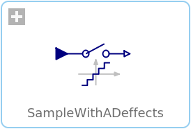
SampleWithADeffectsSample with (simulated) Analog-Digital converter effects including noise |
|
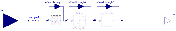
Diagram
Wolfram Language
In[1]:=
SystemModel["Modelica_Synchronous.RealSignals.Sampler.SampleWithADeffects"]
Out[1]:=
Information
This block is similar to the
Sample
block. The only difference is that after the sampling of the input signal,
simulated real-world effects are applied on the sampled signal. In particular:
- The output is limited, if parameter limited = true.
- The output is value discretized in the form of an Analog-Digital converter with a defineable number of bits, if parameters limited = true, and quantized = true.
- Noise is added to the output if parameter noisy = true. A pseudo random number generator is used to generate uniformly distributed random numbers in a given band.
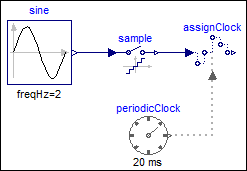
Example
The following example samples a sine signal with a periodic clock of 20 ms period, and adds the following effects:
- Limits the output to +/- 0.8.
- Discretizes the output with an 8 bit AD converter.
- Adds large uniform noise with a band of +/- 0.2.
 |
 |
|
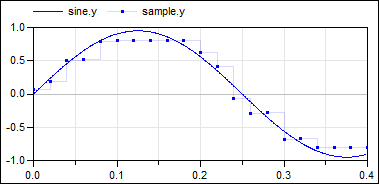
| model | simulation result |
The output y is quite far away from the continuous-time input signal,
due to the strong discretization and large noise applied to the
sampled input.
Parameters (6)
| noisy |
Value: false Type: Boolean Description: = true, if output should be superimposed with noise |
|---|---|
| limited |
Value: false Type: Boolean Description: = true, if output is limited |
| quantized |
Value: false Type: Boolean Description: = true, if output quantization effects included |
| yMax |
Value: 1 Type: Real Description: Upper limit of output (if limited = true) |
| yMin |
Value: -yMax Type: Real Description: Lower limit of output (if limited = true) |
| bits |
Value: 8 Type: Integer Description: Number of bits of quantization (if quantized = true) |
Connectors (9)
| u |
Type: RealInput Description: Connector of continuous-time, Real input signal |
|
|---|---|---|
| y |
Type: RealOutput Description: Connector of clocked, Real output signal |
|
| uFeedthrough1 |
Type: RealInput Description: 'input Real' as connector |
|
| uFeedthrough2 |
Type: RealInput Description: 'input Real' as connector |
|
| uFeedthrough3 |
Type: RealInput Description: 'input Real' as connector |
|
| y1 |
Type: RealOutput Description: Connector with a Real output signal |
|
| y2 |
Type: RealOutput Description: 'output Real' as connector |
|
| y3 |
Type: RealOutput Description: 'output Real' as connector |
|
| y4 |
Type: RealOutput Description: 'output Real' as connector |
Components (4)
| sample1 |
Type: Sample Description: Sample the continuous-time, Real input signal and provide it as clocked output signal (clock is inferred) |
|
|---|---|---|
| noise |
Type: UniformNoise Description: Noise model |
|
| limiter |
Type: Limiter Description: Limit the range of a signal |
|
| quantization |
Type: Quantization Description: DAC quantization effects |
Used in Examples (5)
|
Modelica_Synchronous.Examples.SimpleControlledDrive Simple controlled drive with discrete controller and simulated AD and DA effects |
|
|
Modelica_Synchronous.Examples.Elementary.RealSignals Example of a SampleWithADeffects block for Real signals |
|
|
Modelica_Synchronous.WorkInProgress.Tests Using partial sample and hold blocks to allow redeclaration of blocks to simulated communication blocks |
|
|
Modelica_Synchronous.WorkInProgress.Tests |
|
|
Modelica_Synchronous.WorkInProgress.Tests |