InputOutputResponse[sys,u,tspec]
gives the response of the input-output model sys with input signals u and temporal specification tspec.
InputOutputResponse[sys,…,"prop"]
gives the value of property "prop".


InputOutputResponse
InputOutputResponse[sys,u,tspec]
gives the response of the input-output model sys with input signals u and temporal specification tspec.
InputOutputResponse[sys,…,"prop"]
gives the value of property "prop".
Details and Options
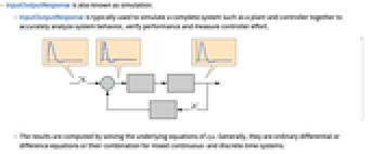
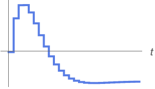
- InputOutputResponse is also known as simulation.
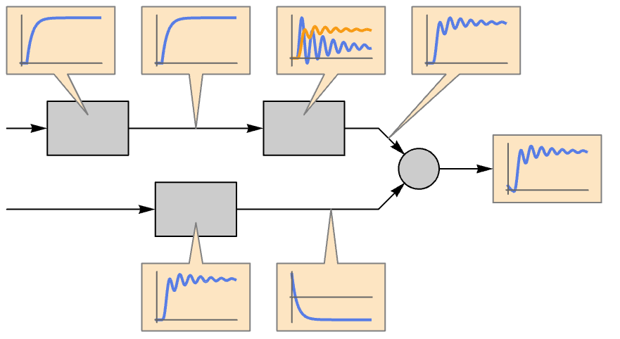
- InputOutputResponse is typically used to simulate a complete system such as a plant and controller together to accurately analyze system behavior, verify performance and measure controller effort.
- The results are computed by solving the underlying equations of sys. Generally, they are ordinary differential or difference equations or their combination for mixed continuous- and discrete-time systems.
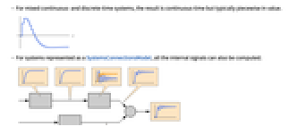
- For mixed continuous- and discrete-time systems, the result is continuous-time but typically piecewise in value.
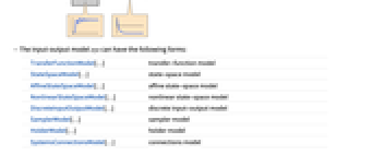
- For systems represented as a SystemsConnectionsModel, all the internal signals can also be computed.
- The input-output model sys can have the following forms:
-
TransferFunctionModel[…] transfer-function model StateSpaceModel[…] state-space model AffineStateSpaceModel[…] affine state-space model NonlinearStateSpaceModel[…] nonlinear state-space model DiscreteInputOutputModel[…] discrete input-output model SamplerModel[…] sampler model HolderModel[…] holder model SystemsConnectionsModel[…] connections model - InputOutputResponse[{sys,ics},…] can be used to specify initial conditions ics.
- The input signal u can have the following forms:
-
{u1[t],…,up[t]} continuous-time signals ui[t] as functions of time t {{u11,…,u1k},…,{up1,…,upk}} discrete-time signal sequences {ui1,…,uik} {…,ui[t],…,{uj1,…,ujk},…} a combination of continuous- and discrete-time signals - The temporal specification tspec can have the following forms:
-
t compute the symbolic solution as a function of 
{t,0,tmax} compute the numeric or symbolic solution for 
- The property "prop" can have the following forms:
-
"Data" the InputOutputResponseData object "OutputResponse" output response as a list "OutputResponseAssociation" the output response as an association "PropertyAssociation" property names and values as an association "PropertyDataset" property names and values as a Dataset "StateResponse" state response as a list "StateResponseAssociation" - state response as an association
"SubsystemOutputResponse" output response of subsystems as a list "SubsystemOutputResponseAssociation" output response of subsystems as an association {p1,p2,…} values of properties pi - InputOutputResponse accepts a Method option that can take the following values:
-
"DSolve" DSolve "Integrate" Integrate "Iterate" iterate to get the solution "NDSolve" NDSolve "RecurrenceTable" RecurrenceTable "RSolve" RSolve "Sum" Sum - With Method{m,opt1val1,…}, method m is used with option opti set to value vali.
Examples
open all close allBasic Examples (4)
Scope (31)
Basic Uses (9)
Simulate the response of a system to a unit-step input:
Compute the response of a state-space model:
The response starts from the specified values:
The response of a multiple-input system:
If fewer signals are specified, default values that are usually 0 are chosen for the remaining inputs:
For discrete-time systems, the input signal is a discrete sequence:
An input sequence can be generated from a time specification:
The input sequence is generated taking the sampling period of the system into consideration:
Specifying the input sequence directly gives the same result:
Models (11)
The response of a transfer-function model to a sinusoid:
The response of a state-space model to a unit-step input:
The response of a delay model to a sinusoid:
The response of the system with no delays:
The response of a descriptor model to a unit-step input:
The response of an affine state-space model:
A nonlinear state-space model:
A discrete input-output model:
Obtain the responses of the subsystems of a sampled data system:

Properties (11)
Compute the data object first:
Obtain properties from the data object:
Obtain all properties as an association:
Obtain all properties as a dataset:
The state response as an association:

Obtain the state response of the fourth subsystem:
The output response as an association:
The output response of the subsystems:
Properties & Relations (2)
Superposition principle for linear systems:
The additive property states that the response to a sum of inputs is the same as the sum of the responses to individual inputs:
The homogeneity property states that the response to an input multiplied by a scalar is the same as the response multiplied by the same scalar:
The sinusoidal responses of linear systems can be seen in a Bode plot:
The response of the system to an input signal of frequency ![]() :
:
After the transients are gone, the response is essentially identical to the input signal:
The gain is 1 and the phase lead is 0:
The response of the system to an input signal of frequency ![]() :
:
After the transients are gone, the response is another pure sinusoid:
Compute a time instance when the response peaks:
Compute a time instance when the input signal peaks:
Points on the Bode magnitude plot for the two input sinusoids:
Related Guides
History
Text
Wolfram Research (2024), InputOutputResponse, Wolfram Language function, https://reference.wolfram.com/language/ref/InputOutputResponse.html.
CMS
Wolfram Language. 2024. "InputOutputResponse." Wolfram Language & System Documentation Center. Wolfram Research. https://reference.wolfram.com/language/ref/InputOutputResponse.html.
APA
Wolfram Language. (2024). InputOutputResponse. Wolfram Language & System Documentation Center. Retrieved from https://reference.wolfram.com/language/ref/InputOutputResponse.html
BibTeX
@misc{reference.wolfram_2025_inputoutputresponse, author="Wolfram Research", title="{InputOutputResponse}", year="2024", howpublished="\url{https://reference.wolfram.com/language/ref/InputOutputResponse.html}", note=[Accessed: 06-February-2026]}
BibLaTeX
@online{reference.wolfram_2025_inputoutputresponse, organization={Wolfram Research}, title={InputOutputResponse}, year={2024}, url={https://reference.wolfram.com/language/ref/InputOutputResponse.html}, note=[Accessed: 06-February-2026]}