WOLFRAM SYSTEM MODELER
LinearPositionPIDControl position of the quadrotor through PID controllers |
|
Diagram
Wolfram Language
In[1]:=
SystemModel["Aircraft.ControlSystems.MultiRotorControllers.LinearPositionPID"]
Out[1]:=
Information
The primary objective of the control design considered in our study is to achieve stable positioning for the unmanned aerial vehicle (UAV) by maintaining a constant set point. To overcome the inherent underactuation challenges associated with vectored-thrust UAVs, we employ a hierarchical control strategy that effectively utilizes the attitude dynamics to stabilize the translational dynamics.
The linear position is in the inertial frame; the inputs from the sensors are relative to the inertia frame.
The translational controller receives user-defined reference positions as inputs and utilizes feedback to obtain the measured linear velocity and position of the quadrotor. By employing LimPID controllers, the translational controller aims to regulate the translational dynamics of the quadrotor. Additionally, it generates reference rotation angles, roll (φ) and (θ), which are subsequently transmitted to the attitude controller. [1]

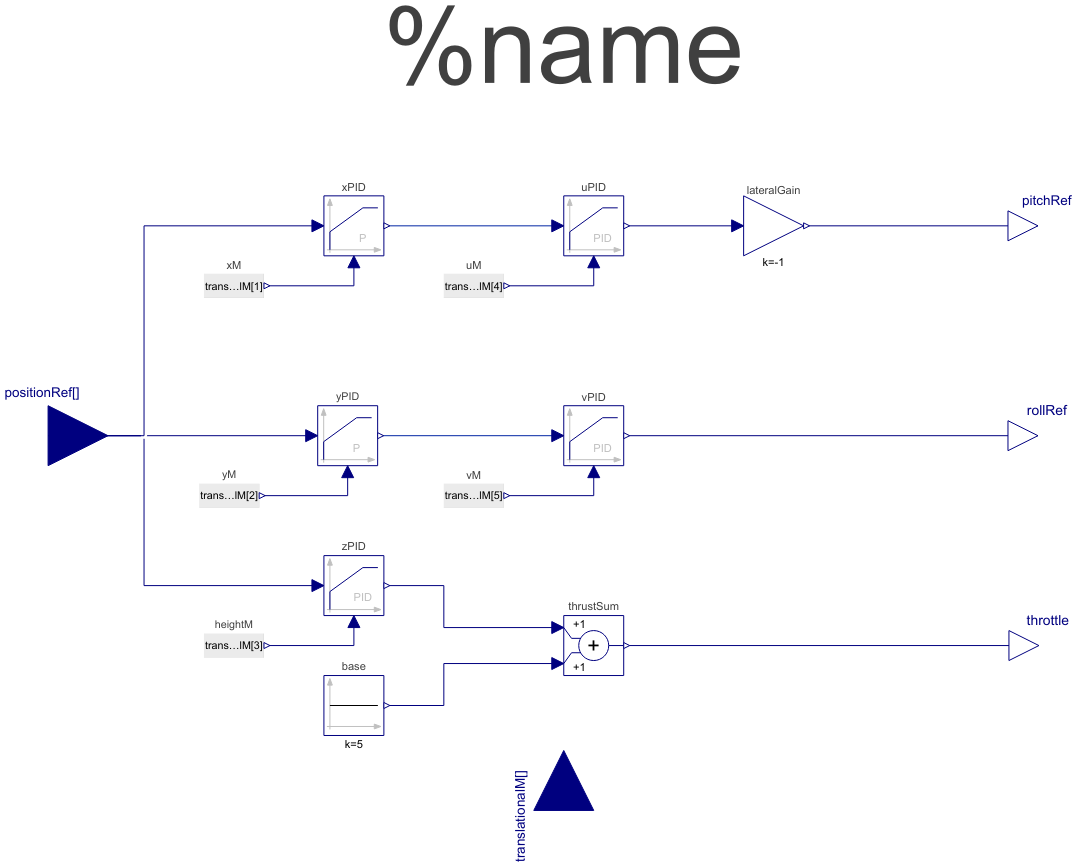
Figure 1: Controller block diagram.
Figure 1 demonstrates the block diagram of the position controller. It employs a cascade P-PID controller for both longitudinal and lateral control channels, along with a PID controller for height control.
In-depth, in the longitudinal control, the reference x position is determined by user input, and it is subtracted from the quadrotor's measured x position (x Measured) from the sensor to calculate the x position error (xe). This error is then passed to a proportional (P) controller. The output of the x position controller is the reference longitudinal velocity, denoted as uref. Utilizing the measured longitudinal velocity (uMeasured), the velocity error (ve) is processed through a LimPID controller, generating the reference pitch angle (θref) for input into the attitude controller. This LimPID controller generates the reference pitch angle, which is then fed into the attitude controller.
The same approach is applied to the lateral channel control for controlling the quadrotor's lateral position.
The quadrotor's vertical position (z) is regulated by a LimPID controller, which produces the throttle increment command for altitude adjustment. The base thrust, which represents the minimum required thrust to overcome the weight of the quadrotor, should be added to the thrust increment.This net command is then sent to Mixer, where the allocation of forces and moments takes place, enabling the generation of the appropriate motion.
When comparing this controller to the PositionAttitude controller, the structure of this controller is more accurate because it possesses greater information regarding the quadrotor, including velocity feedback. However, it is less stable, particularly when subjected to rapid changes in input.
LimPID
The LimPID controller can be finely adjusted by modifying its proportional gain, integrator, derivative time constants and saturation limit. The saturation limit can be configured within the constraints defined by yMax and yMin, taking into account model limitations such as actuator deflection limits or motor RPM. Once the controller type in LimPID is selected, a combination of proportional, derivative and integral controllers can be configured to meet the desired control objectives.
Note: The controller gains should be tuned based on the specific quadrotor and mission requirements.
References
[1]: Giurato, M. (2020). Design, integration and control of multirotor UAV platforms.
Parameters (11)
| propGainXPID |
Value: 3 Type: Real Description: Gain of the logitudinal position (x) PID controller |
|---|---|
| propGainYPID |
Value: 3 Type: Real Description: Gain of the lateral position (y) PID controller |
| propGainUPID |
Value: 1 Type: Real Description: Gain of the longitudinal velocity (x) PID controller |
| intTimeConstUPID |
Value: 200 Type: Time (s) Description: Time constant of Integrator block of the longitudinal velocity (x) PID controller |
| derTimeConstUPID |
Value: 0.001 Type: Time (s) Description: Time constant of Derivative block of the longitudinal velocity (x) PID controller |
| propGainVPID |
Value: 1 Type: Real Description: Gain of lateral velocity (v) PID controller |
| intTimeConstVPID |
Value: 200 Type: Time (s) Description: Time constant of Integrator block of the lateral velocity (v) PID controller |
| derTimeConstVPID |
Value: 0.001 Type: Time (s) Description: Time constant of Derivative block of the lateral velocity (v) PID controller |
| propGainHeightPID |
Value: 100 Type: Real Description: Gain of the height (z) controller |
| intTimeConstHeightPID |
Value: 2 Type: Time (s) Description: Time constant of Integrator block of the height (z) controller |
| derTimeConstHeightPID |
Value: 0.1 Type: Time (s) Description: Time constant of Derivative block of the height (z) controller |
Connectors (5)
| positionRef |
Type: RealInput[3] Description: Reference position vector |
|
|---|---|---|
| translationalM |
Type: RealInput[6] Description: Measured x position |
|
| rollRef |
Type: RealOutput Description: Reference roll angle |
|
| pitchRef |
Type: RealOutput Description: Reference pitch angle |
|
| throttle |
Type: RealOutput Description: Throtle command |
Components (13)
| uPID |
Type: LimPID Description: PID controller generates pitch angle control command |
|
|---|---|---|
| vPID |
Type: LimPID Description: PID controller generates roll angle control command |
|
| xPID |
Type: LimPID Description: Proportional controller generates longitudinal velocity (u) |
|
| yPID |
Type: LimPID Description: Proportional controller generates lateral velocity (v) |
|
| zPID |
Type: LimPID Description: PID controller generates the throttle command |
|
| lateralGain |
Type: Gain Description: The gain command reversing the lateral reference roll angle |
|
| xM |
Type: RealExpression Description: Measured x position |
|
| uM |
Type: RealExpression Description: Measured longitudinal velocity |
|
| yM |
Type: RealExpression Description: Measured y position |
|
| vM |
Type: RealExpression Description: Measured lateral velocity |
|
| heightM |
Type: RealExpression Description: Measured z position (height) |
|
| thrustSum |
Type: Add Description: The total of the basic thrust and the incremental thrust |
|
| base |
Type: Constant Description: Base thrust value equivalent to the quadrotor weight |
Used in Examples (1)
|
Aircraft.Examples Compare the impact of two types of controller structures on the motion of the quadrotor |