WOLFRAM SYSTEM MODELER
InvertedPendulumPulseA LQR-controlled inverted pendulum system |
|
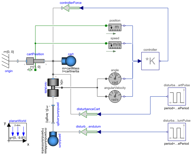
Diagram
Wolfram Language
In[1]:=
SystemModel["EducationExamples.MechanicalEngineering.InvertedPendulum.InvertedPendulumPulse"]
Out[1]:=
Information
Library Dependency
This model requires the ModelPlug and PlanarMechanics libraries.
- ModelPlug is a free Modelica library that allows you to link your simulation models to the real world by the use of an Arduino Board or any other board following the Firmata protocol). ModelPlug opens up a wide variety of ways to interact with your models, for example by using buttons, switches, input sensor information or even actuators such as motors and servos.
- The free PlanarMechanics library was created especially for modeling multibody systems with two-dimensional mechanical components. Compared to the MultiBody library, currently available in the Modelica Standard Library, it is simpler to use and it is more optimized to planar modeling. Planar models of mechanical systems are useful in many different applications, for example, in contact problems that are more easily modeled in 2D than in 3D.
Model
The inverted pendulum model consists of a pendulum and a cart, with the axis of rotation of the pendulum being located at the center of the cart. The pendulum is initialized with its center of mass above the rotation axis. When located directly above the cart, the pendulum will be in steady state and will stay there until disturbed.
While a pendulum that hangs straight down will be in a stable position, an inverted pendulum is unstable. That means that any small disturbance will cause the pendulum to tip over and never return to its original position.
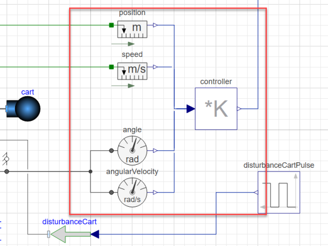
Control System
A control system can be used to stabilize the unstable pendulum. Here, a linear-quadratic regulator is used. First, the regulator measures the states of the system, namely the cart position and velocity, the pendulum angle and the angular velocity. The regulator then calculates a force that should be applied on the cart in order for all the states to become zero. In other words, the regulator aims to have the pendulum pointing straight up (defined here as 0 degrees) and the cart return to the origin.
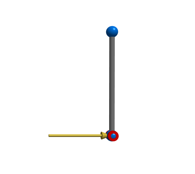
Simulation
By simulating the model, you can try different values of the parameters and see how the control system responds.
To simulate the model and see the generated 3D animation, follow the steps below:
Click the Simulate button:
When the simulation is finished, click the Animate button: 
Use your mouse or trackpad to drag the animation into a good angle and zoom in with your scroll wheel or by using the trackpad. Then click the Play button to play the animation: 
You can change the magnitude of the force that is applied to the pendulum by changing the pendulumDisturbanceForce parameter.
Parameters (9)
| cartMass |
Value: 1 Type: Mass (kg) Description: Mass of the cart (base of the pendulum) |
|---|---|
| cartInertia |
Value: 0.1 Type: Inertia (kg⋅m²) Description: Inertia of the cart (base of the pendulum) |
| pendulumMass |
Value: 0.5 Type: Mass (kg) Description: Mass at the top of the pendulum |
| pendulumInertia |
Value: 0.1 Type: Inertia (kg⋅m²) Description: Inertia at the top of the pendulum |
| angle0 |
Value: 0 Type: Angle (rad) Description: Initial angle of the pendulum |
| cartDisturbanceForce |
Value: 0.1 Type: Force (N) Description: Ampliude of disturbance force applied to cart |
| pendulumDisturbanceForce |
Value: 1.5 Type: Force (N) Description: Ampliude of disturbance force applied to the top of the pendulum |
| cartDisturbancePeriod |
Value: 4 Type: Time (s) Description: Period of the disturbance pulse on the cart |
| pendulumDisturbancePeriod |
Value: 1 Type: Time (s) Description: Period of the disturbance pulse on the top of the pendulum |
Connectors (5)
| s |
Type: RealOutput Description: Absolute position of flange as output signal (position.s) |
|
|---|---|---|
| v |
Type: RealOutput Description: Absolute velocity of flange as output signal (speed.v) |
|
| phi |
Type: RealOutput Description: Absolute angle of flange as output signal (angle.phi) |
|
| w |
Type: RealOutput Description: Absolute angular velocity of flange as output signal (angularVelocity.w) |
|
| y |
Type: RealOutput[controller.nout] Description: Connector of Real output signals (controller.y) |
Components (17)
| pendulum |
Type: Body Description: Pendulum mass. |
|
|---|---|---|
| origin |
Type: Fixed Description: Center point. Reference point for cart. |
|
| cart |
Type: Body Description: Mass of cart. |
|
| planarWorld |
Type: PlanarWorld Description: Planar world coordinate system + gravity field + default animation definition |
|
| revolute |
Type: Revolute Description: Pendulum axis of rotation. |
|
| cartPosition |
Type: Prismatic Description: Translational position of cart. |
|
| angle |
Type: AngleSensor Description: Angle sensor for the pendulum. |
|
| controller |
Type: MatrixGain Description: LQ-regulator with optimal gains. |
|
| position |
Type: PositionSensor Description: Position sensor for the cart. |
|
| angularVelocity |
Type: SpeedSensor Description: Velocity sensor for the pendulum. |
|
| speed |
Type: SpeedSensor Description: Velocity sensor for the cart. |
|
| disturbancePendulum |
Type: WorldForce Description: Disturbance force applied on the pendulum. |
|
| disturbanceCart |
Type: WorldForce Description: Disturbance force applied on the cart. |
|
| pendulumLength |
Type: FixedTranslation Description: Length of the pendulum. |
|
| controllerForce |
Type: WorldForce Description: Corrective force applied to the cart. |
|
| disturbanceCartPulse |
Type: Pulse Description: Magnitude of disturbance force applied on the cart. |
|
| disturbancePendulumPulse |
Type: Pulse Description: Magnitude of disturbance force applied on the pendulum. |