WOLFRAM SYSTEM MODELER
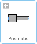
PrismaticA prismatic joint |
|
Diagram

Wolfram Language
In[1]:=
SystemModel["PlanarMechanics.Joints.Prismatic"]
Out[1]:=
Information
Direction of the prismatic joint is determined by r[2],
which is a vector pointing from frame_a to
frame_b.
Optionally, two additional one-dimensional mechanical flanges (flange
flange_a represents the driving flange and flange
support represents the bearing) can be enabled via
parameter useFlange. The enabled flange_a
flange can be driven with elements of the
Modelica.Mechanics.Translational
library.
In the "Initialization" block, elongation s
of the joint, velocity of elongation v as well as
acceleration of elongation a can be initialized.
It can be defined via parameter (in "Advanced" tab)
stateSelect that the relative distance s
and its derivative shall be definitely used as states by setting
stateSelect = StateSelect.always.
In "Animation" group, animation parameters for this model can be set,
where zPosition represents the model's position along
the z axis in 3D animation. Some of the values can be preset
by an outer PlanarWorld
model.
Parameters (8)
| useFlange |
Value: false Type: Boolean Description: = true, if force flange enabled, otherwise implicitly grounded |
|---|---|
| animate |
Value: true Type: Boolean Description: = true, if animation shall be enabled |
| stateSelect |
Value: StateSelect.default Type: StateSelect Description: Priority to use s and v as states |
| r |
Type: Position[2] (m) Description: Direction of the rod wrt. body system at phi=0 |
| l |
Value: Modelica.Math.Vectors.length(r) Type: Length (m) Description: Length of r |
| e |
Value: Modelica.Math.Vectors.normalizeWithAssert(r) Type: Real[2] Description: Unit vector in direction of r |
| zPosition |
Value: planarWorld.defaultZPosition Type: Length (m) Description: Position z of the prismatic joint box |
| boxWidth |
Value: l / planarWorld.defaultWidthFraction Type: Distance (m) Description: Width of prismatic joint box |
Inputs (2)
| boxColor |
Default Value: Types.Defaults.JointColor Type: Color Description: Color of prismatic joint box |
|---|---|
| specularCoefficient |
Default Value: planarWorld.defaultSpecularCoefficient Type: SpecularCoefficient Description: Reflection of ambient light (= 0: light is completely absorbed) |
Connectors (4)
| frame_a |
Type: Frame_a Description: Coordinate system fixed to the component with one cut-force and cut-torque |
|
|---|---|---|
| frame_b |
Type: Frame_b Description: Coordinate system fixed to the component with one cut-force and cut-torque |
|
| flange_a |
Type: Flange_a Description: One-dimensional translational flange (left, flange axis directed INTO cut plane) |
|
| support |
Type: Flange_b Description: 1-dim. translational flange of the drive support (assumed to be fixed in the world frame, NOT in the joint) |
Components (3)
| planarWorld |
Type: PlanarWorld Description: Planar world model |
|
|---|---|---|
| box |
Type: Shape Description: Visualizing an elementary object with variable size; all data have to be set as modifiers (see info layer) |
|
| fixed |
Type: Fixed Description: Fixed flange |
Used in Examples (13)
|
PlanarMechanics.Examples Power and distance sensor demo |
|
|
PlanarMechanics.Examples A damped crane crab |
|
|
PlanarMechanics.Examples A controlled crane crab |
|
|
PlanarMechanics.Examples An inverted model of a pendulum |
|
|
PlanarMechanics.Examples Spring demo |
|
|
PlanarMechanics.Examples An example of a kinematic loop (manual state selection) |
|
|
KinematicLoop_DynamicStateSelection PlanarMechanics.Examples An example of a kinematic loop |
|
|
PlanarMechanics.Examples A piston engine (manual state selection) |
|
|
PistonEngine_DynamicStateSelection PlanarMechanics.Examples A piston engine |
|
|
PlanarMechanics.Examples A damped crane crab |
|
|
PlanarMechanics.VehicleComponents.Examples Test an ideal wheel |
|
|
PlanarMechanics.VehicleComponents.Examples Dry friction wheel |
|
|
PlanarMechanics.VehicleComponents.Examples A slip-based wheel |
Revisions
 Developed 2010 at the DLR Institute of System Dynamics and Control