AnglePath3D[{{α1,β1,γ1},{α2,β2,γ2},…}]
{0,0,0}から始まり,それぞれがオイラー角 αi,βi,γiによるオブジェクトの連続的な回転の結果である
軸方向に単位長の一連のステップを取る,オブジェクトの経路の3D座標のリストを与える.
AnglePath3D[{{α1,β1},{α2,β2},…}]
オイラー角 γiが0であると仮定する.
AnglePath3D[{mat1,mat2,…}]
連続する回転が3D回転行列 matiで指定されるとみなす.
AnglePath3D[{{r1,rot1},{r2,rot2},…}]
rotiで指定されたオイラー角あるいは回転行列で長さ riの連続するステップを取る.
AnglePath3D[{x0,y0,z0},steps]
点{x0,y0,z0}から開始する.
AnglePath3D[{rot0},steps]
オイラー角または回転行列 rot0に従ってオブジェクトを回転させることで指定された
軸方向に進む.
AnglePath3D[{{x0,y0,z0},rot0},steps]
rot0で指定された
軸方向で点{x0,y0,z0}から開始する.
AnglePath3D[init,steps,form]
各ステップで,form で指定された形のデータを返す.
AnglePath3D
AnglePath3D[{{α1,β1,γ1},{α2,β2,γ2},…}]
{0,0,0}から始まり,それぞれがオイラー角 αi,βi,γiによるオブジェクトの連続的な回転の結果である
軸方向に単位長の一連のステップを取る,オブジェクトの経路の3D座標のリストを与える.
AnglePath3D[{{α1,β1},{α2,β2},…}]
オイラー角 γiが0であると仮定する.
AnglePath3D[{mat1,mat2,…}]
連続する回転が3D回転行列 matiで指定されるとみなす.
AnglePath3D[{{r1,rot1},{r2,rot2},…}]
rotiで指定されたオイラー角あるいは回転行列で長さ riの連続するステップを取る.
AnglePath3D[{x0,y0,z0},steps]
点{x0,y0,z0}から開始する.
AnglePath3D[{rot0},steps]
オイラー角または回転行列 rot0に従ってオブジェクトを回転させることで指定された
軸方向に進む.
AnglePath3D[{{x0,y0,z0},rot0},steps]
rot0で指定された
軸方向で点{x0,y0,z0}から開始する.
AnglePath3D[init,steps,form]
各ステップで,form で指定された形のデータを返す.
詳細とオプション
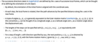
- AnglePath3Dが連続的に取る方向は,連続する局所フレームの
軸で決定される.これは,3Dオブジェクの向きを定義すると考えることができる. - デフォルトで,初期フレームの向きは座標軸と揃っている.
- 各ステップで,局所フレームは回転され,経路は新たなフレーム内で指定された距離だけ
軸に沿って進む. - 3つ一組の角度{αi,βi,γi}は,一般に,オイラーの回転行列EulerMatrix[{αi,βi,γi},{3,2,1}]に等しい.この表記法では,αiは経度角, βiは緯度角,γiは変位軸の周りの回転角である.
- ステップ長は{{r1,rot1},{r2,rot2},…}で,あるいは同様に{{r1,r2,…},{rot1,rot2,…}}で指定することができる.
- 方向が matiで指定された長さ riのステップについては,次の位置 pi={xi,yi,zi}を pi=pi-1+fi.{ri,0,0}で得ることができる.フレームの回転行列 fiは fi=fi-1.matiおよび f0=mat0で与えられる.
- AnglePath3D[steps,form]はAnglePath3D[{0,0,0},steps,form]に等しい.
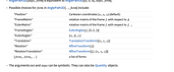
- AnglePath3D[…,form]の form は以下から選ぶことができる.
-
"Position" 直交座標{xi,yi,zi}(デフォルト) "FrameMatrix" フレーム fiの f0に対する回転行列 "EulerMatrix" フレーム fiのフレーム fi - 1に対する回転行列 "FrameAngles" EulerAngles[fi,{3,2,1}] "EulerAngles" {αi,βi,γi} "Translation" TranslationTransform[{xi,yi,zi}] "Rotation" AffineTransform[fi] "RotationTranslation" AffineTransform[{fi,{xi,yi,zi}}] {form1,form2,…} 形のリスト - 引数 init および steps は記号的でもよく,Quantityオブジェクトでもよい.
- AnglePath3DにはオプションWorkingPrecisionがある.このオプションは生成する数の精度を決定する.
- デフォルト設定のWorkingPrecisionAutomaticでは,短いパスに対してのみ厳密な入力に対して厳密数が生成される.パスが長くなると機械精度が使われる.
例題
すべて開く すべて閉じる例 (6)
{0,0,0}から始め
軸に沿って単位ステップをいくつか動く.その際,各ステップで局所
軸について90°回転する:
AnglePath3D[{{90°, 0, 0}, {90°, 0, 0}, {90°, 0, 0}}]局所フレームを局所の
,
,
軸についてオイラー角で30°,30°,90°回転させて,いくつかの単位ステップ分動く:
AnglePath3D[{{30°, 30°, 90°}, {30°, 30°, 90°}, {30°, 30°, 90°}}]別々の長さのステップで動く.その際,局所フレームを局所
軸および
軸に対してオイラー角で90°回転させる:
AnglePath3D[{{1, {90°, 90°}}, {2, {90°, 90°}}, {3, {90°, 90°}}}]20ステップ進む.常に局所フレームをすべての軸に対してオイラー角で100°回転させる:
Graphics3D[Tube[AnglePath3D[ConstantArray[{100.°, 100.°, 100.°}, 20]]], Boxed -> False]pos = AnglePath3D[ConstantArray[N@{0, -π / 12, π / 25}, 100]];Graphics3D[Arrow[pos]]transformations = AnglePath3D[{{7, {π / 2, 0}}, {9, {0, π / 2}}}, "RotationTranslation"]triceratops = ExampleData[{"Geometry3D", "Triceratops"}, "GraphicsComplex"];
Graphics3D[GeometricTransformation[triceratops, transformations]]AnglePath3D[{{0, 0, Subscript[γ, 1]}, {0, Subscript[β, 2], 0}, {Subscript[α, 3], 0, 0}}]スコープ (22)
ステップ指定 (7)
軸の方向に位置{0,0,0}から始まる3つの角が1組みになったオイラー角で単位ステップの経路を生成する:
AnglePath3D[{{90°, 0, 30°}, {60°, -120°, 0}, {0, 180°, -45°}}]AnglePath3D[{{π / 3, 0}, {π / 2, -2π / 3}, {0, π}}]AnglePath3D[{{α1,β1},{α2,β2},…}]は,3番目のオイラー角が0であると仮定する:
path1 = AnglePath3D[{{Subscript[α, 1], Subscript[β, 1]}, {Subscript[α, 2], Subscript[β, 2]}, {Subscript[α, 3], Subscript[β, 3]}}];
path2 = AnglePath3D[{{Subscript[α, 1], Subscript[β, 1], 0}, {Subscript[α, 2], Subscript[β, 2], 0}, {Subscript[α, 3], Subscript[β, 3], 0}}];path1 === path2lengths = {2, 5, 7};
angles = {{0, π / 2, -5π / 6}, {3π / 2, 0, π / 3}, {0, -π / 3, 0}};AnglePath3D[{lengths, angles}]ステップの長さと方向は,繋げて与えることも別々に与えることもできる:
path1 = AnglePath3D[{{Subscript[r, 1], {Subscript[α, 1], Subscript[β, 1], Subscript[γ, 1]}}, {Subscript[r, 2], {Subscript[α, 2], Subscript[β, 2], Subscript[γ, 2]}}, {Subscript[r, 3], {Subscript[α, 3], Subscript[β, 3], Subscript[γ, 3]}}}];
path2 = AnglePath3D[{{Subscript[r, 1], Subscript[r, 2], Subscript[r, 3]}, {{Subscript[α, 1], Subscript[β, 1], Subscript[γ, 1]}, {Subscript[α, 2], Subscript[β, 2], Subscript[γ, 2]}, {Subscript[α, 3], Subscript[β, 3], Subscript[γ, 3]}}}];path1 === path2mat1 = {{1 / 2, -Sqrt[3] / 2, 0}, {Sqrt[3] / 2, 1 / 2, 0}, {0, 0, 1}};
mat2 = {{0, -1, 0}, {-1 / 2, 0, -Sqrt[3] / 2}, {Sqrt[3] / 2, 0, -1 / 2}};AnglePath3D[{mat1, mat2}]入力でQuantityオブジェクトを使う:
lengths = Quantity[{2, 5, 7}, "Meters"];
angles = Quantity[{{4.6, 2.7}, {0.4, 3.2}, {1.5, 8.6}}, "Radians"];AnglePath3D[{lengths, angles}]経路の初期化 (7)
steps = {{90°, 0, 30°}, {60°, -120°, 0}, {0, 180°, -45°}};
p0 = {5, 15, 10};AnglePath3D[p0, steps]3つの角が1組みになったオイラー角を与えて初期フレームの向きを選択する:
steps = {{90°, 0, 30°}, {60°, -120°, 0}, {0, 180°, -45°}};
ang0 = {π / 6, 0, π};AnglePath3D[{ang0}, steps]steps = {{90°, 0, 30°}, {60°, -120°, 0}, {0, 180°, -45°}};
ang0 = {-π / 3, π / 2};AnglePath3D[{ang0}, steps]steps = {{90°, 0, 30°}, {60°, -120°, 0}, {0, 180°, -45°}};
mat0 = {{0, Sqrt[3] / 2, 1 / 2}, {0, 1 / 2, -Sqrt[3] / 2}, {-1, 0, 0}};AnglePath3D[{mat0}, steps]初期の位置と初期の向きの両方が指定されている経路を生成する:
steps = {{90°, 0, 30°}, {60°, -120°, 0}, {0, 180°, -45°}};
p0 = {5, 15, 10};
ang0 = {π / 6, 0, π};AnglePath3D[{p0, ang0}, steps]path1 = AnglePath3D[
{{x, y, z}, {Subscript[α, 0], Subscript[β, 0], Subscript[γ, 0]}}, {{Subscript[r, 1], Subscript[r, 2]}, {{Subscript[α, 1], Subscript[β, 1], Subscript[γ, 1]}, {Subscript[α, 2], Subscript[β, 2], Subscript[γ, 2]}}}
];path2 = AnglePath3D[
{x, y, z}, {{0, Subscript[r, 1], Subscript[r, 2]}, {{Subscript[α, 0], Subscript[β, 0], Subscript[γ, 0]}, {Subscript[α, 1], Subscript[β, 1], Subscript[γ, 1]}, {Subscript[α, 2], Subscript[β, 2], Subscript[γ, 2]}}}
];path1 === Rest@path2入力でQuantityオブジェクトを使う:
initpos = Quantity[{2, 4, 3}, "Meters"];
lengths = Quantity[{2, 5, 7}, "Meters"];
angles = Quantity[{{4.6, 2.7}, {0.4, 3.2}, {1.5, 8.6}}, "Radians"];AnglePath3D[initpos, {lengths, angles}]データの形式 (8)
デフォルトで,AnglePath3Dは各ステップで到達した点の位置を返す:
rots = {{Subscript[α, 1], Subscript[β, 1], Subscript[γ, 1]}, {Subscript[α, 2], Subscript[β, 2], Subscript[γ, 2]}, {Subscript[α, 3], Subscript[β, 3], Subscript[γ, 3]}};pos1 = AnglePath3D[rots];
pos2 = AnglePath3D[rots, "Position"];pos1 === pos2pos1 = AnglePath3D[{a, b, c}, rots];
pos2 = AnglePath3D[{a, b, c}, rots, "Position"];pos1 === pos2AnglePath3D[{{π / 3, 0}, {π / 2, -2π / 3}}, "EulerMatrix"];Map[MatrixForm, %]AnglePath3D[{{π / 3, 0}, {π / 2, -2π / 3}}, "FrameMatrix"];Map[MatrixForm, %]大域的フレーム内の各局所フレームの向きを決定するオイラー角を計算する:
AnglePath3D[{{π / 3, 0}, {π / 2, -2π / 3}}, "FrameAngles"]translations = AnglePath3D[{{4, {π / 2, 0}}, {8, {0, -π / 2}}}, "Translation"]ellipsoid = Ellipsoid[{0, 0, 0}, {1, 2, 3}];
Graphics3D[GeometricTransformation[ellipsoid, translations]]rotations = AnglePath3D[{{4, {π / 2, 0}}, {8, {0, -π / 2}}}, "Rotation"]ellipsoid = Ellipsoid[{0, 0, 0}, {1, 2, 3}];
Graphics3D[GeometricTransformation[ellipsoid, rotations]]transformations = AnglePath3D[{{4, {π / 2, 0}}, {8, {0, -π / 2}}}, "RotationTranslation"]ellipsoid = Ellipsoid[{0, 0, 0}, {1, 2, 3}];
Graphics3D[GeometricTransformation[ellipsoid, transformations]]1回のAnglePath3Dの呼出しでデータのさまざまな形を生成する:
forms = {"EulerMatrix", "Position", "RotationTranslation"};
path = AnglePath3D[{{π / 2, 0}, {0, -π / 2}}, forms];3つ1組になったものの最初の要素は,前のフレームに対するオイラー回転である:
Map[MatrixForm, path[[All, 1]]]path[[All, 2]]path[[All, 3]]オプション (1)
WorkingPrecision (1)
デフォルトで,AnglePath3Dはパスが短いときは厳密な入力に対しては厳密数を与え,パスが長くなると機械数を与える:
AnglePath3D[Table[{Pi / 3, 0, 0}, 7]]//LastAnglePath3D[Table[{Pi / 3, 0, 0}, 5004]]//Last作業精度を無限大に指定すると厳密計算が行われるが,計算速度は遅くなる:
AnglePath3D[Table[{Pi / 3, 0, 0}, 5004], WorkingPrecision -> Infinity]//LastAnglePath3D[Table[{Pi / 3, 0, 0}, 7], WorkingPrecision -> 20]//Lastアプリケーション (7)
点様オブジェクトの経路の可視化 (5)
pos = AnglePath3D[ConstantArray[{0, π / 3, 0}, 6]];Graphics3D[Line[pos],
Axes -> True, AxesLabel -> {"X", "Y", "Z"}, Ticks -> None]pos = AnglePath3D[{{π / 2, 0, 0}}, ConstantArray[{0, π / 4, 0}, 8]];Graphics3D[Line[pos],
Axes -> True, AxesLabel -> {"X", "Y", "Z"}, Ticks -> None]rotα = {π / 2, 0};
rotβ = {0, π / 2};
pos = AnglePath3D[{rotα, rotα, rotα, rotβ, rotβ, rotα, rotα}];edges = Graphics3D[{FaceForm[], EdgeForm[Dotted], Cuboid@@CoordinateBoundingBox[pos]}, Boxed -> False]travel = Graphics3D[{Arrowheads[{{.05, .5}}], Arrow /@ Subsequences[pos, {2}], PointSize[Large], Red, Point[pos]}];Show[edges, travel]r = Rest@Subdivide[70];
angles = ConstantArray[{π / 12, 0, -π / 24}, 70];
pos = AnglePath3D[N@{r, angles}];Graphics3D[Arrow[pos]]連続するステップのそれぞれが最大オイラー角で20°方向を変えるランダムウォークを作る:
Graphics3D[Line@AnglePath3D[RandomReal[{-20°, 20°}, {1000, 3}]]]連続するステップのそれぞれがオイラー角で0から
の間で方向を変えるランダムウォークを作る:
Graphics3D[Line@AnglePath3D[RandomReal[{0, π}, {10000, 3}]]]剛体の経路の可視化 (2)
shuttle = GeometricTransformation[ExampleData[{"Geometry3D", "SpaceShuttle"}, "GraphicsComplex"], RotationMatrix[π, {0, 0, 1}].ScalingMatrix[{.05, .05, .05}]];Graphics3D[shuttle, Boxed -> False]pathzaxis = AnglePath3D[{{90°, 0, 0}, {90°, 0, 0}, {90°, 0, 0}}, "RotationTranslation"];Graphics3D[GeometricTransformation[shuttle, pathzaxis], Boxed -> False]path = AnglePath3D[{{90°, 0, 0}, {90°, 0, 0}, {90°, 0, 0}}, {"Position", "RotationTranslation"}];graphics[path_] := Graphics3D[{Dotted, Line[path[[All, 1]]], GeometricTransformation[shuttle, path[[All, 2]]]}, Boxed -> False];graphics[path]pathyaxis = AnglePath3D[{{0, 90°, 0}, {0, 90°, 0}, {0, 90°, 0}}, {"Position", "RotationTranslation"}];graphics[pathyaxis]pathxaxis = AnglePath3D[{{0, 0, 90°}, {0, 0, 90°}, {0, 0, 90°}}, {"Position", "RotationTranslation"}];graphics[pathxaxis]rotα = {π / 2, 0};
rotβ = {0, π / 2};pathA = AnglePath3D[{rotα, rotα, rotα, rotβ, rotβ, rotα, rotα}, {"Position", "RotationTranslation"}];
positions = pathA[[All, 1]];
transformations = pathA[[All, 2]];edges = Graphics3D[{FaceForm[], EdgeForm[Dotted], Cuboid@@CoordinateBoundingBox[positions]}, Boxed -> False];shuttle = GeometricTransformation[ExampleData[{"Geometry3D", "SpaceShuttle"}, "GraphicsComplex"], RotationMatrix[π, {0, 0, 1}].ScalingMatrix[{.03, .03, .03}]];travelA =
Graphics3D[{Arrowheads[{{.03, .5}}], Arrow /@ Subsequences[positions, {2}], GeometricTransformation[shuttle, transformations]}, Boxed -> False];Show[edges, travelA]rotαβ = {π, π / 2};
pathB = AnglePath3D[{rotα, rotα, rotα, rotαβ, -rotβ, -rotα, -rotα}, {"Position", "RotationTranslation"}];positions = pathB[[All, 1]];
transformations = pathB[[All, 2]];travelB = Graphics3D[{Arrowheads[{{.03, .5}}], Arrow /@ Subsequences[positions, {2}], GeometricTransformation[shuttle, transformations]}];Show[edges, travelB]特性と関係 (7)
AnglePath3D[{{θ1,0,0},{θ2,0,0},…}]は
-
平面上の経路を返す:
path3D = AnglePath3D[{{Subscript[θ, 1], 0, 0}, {Subscript[θ, 2], 0, 0}}]path3D[[All, 3]]生成された経路はAnglePath[{θ1,θ2,…}]の経路と等しい:
Simplify[path3D[[All, {1, 2}]] - AnglePath[{Subscript[θ, 1], Subscript[θ, 2]}]]angles = RandomReal[{-Pi, Pi}, {4, 3}]path0 = AnglePath3D[angles, "Position"]path = AnglePath3D[{1, 3, -2}, angles, "Position"]こうすると,すべての点が初期点に対応するベクトル分シフトされる:
path - path0オイラー角を指定することは
-
-
オイラー行列を指定することに等しい:
eulerangles = {{Subscript[α, 1], Subscript[β, 1], Subscript[γ, 1]}, {Subscript[α, 2], Subscript[β, 2], Subscript[γ, 2]}, {Subscript[α, 3], Subscript[β, 3], Subscript[γ, 3]}};
eulermatrices = EulerMatrix[#, {3, 2, 1}]& /@ eulerangles;AnglePath3D[eulerangles] === AnglePath3D[eulermatrices]初期オイラー角を指定することは,初期
-
-
オイラー行列を指定することに等しい:
initialangles = {Subscript[α, 0], Subscript[β, 0], Subscript[γ, 0]};
initialmatrix = EulerMatrix[initialangles, {3, 2, 1}];angles = {{Subscript[α, 1], Subscript[β, 1], Subscript[γ, 1]}, {Subscript[α, 2], Subscript[β, 2], Subscript[γ, 2]}, {Subscript[α, 3], Subscript[β, 3], Subscript[γ, 3]}};AnglePath3D[{initialangles}, angles] === AnglePath3D[{initialmatrix}, angles]ランダムな回転行列の集合を取得し,それに対応する角度の経路を計算する:
rots = EulerMatrix /@ RandomReal[{-Pi, Pi}, {4, 3}]path = AnglePath3D[{0, 0, 0}, rots]この式は,同一の経路を生成するが,進行順序が逆になる回転を計算する:
irots = Prepend[Reverse[Inverse /@ Rest[rots]], -Fold[Dot, rots]]ipath = AnglePath3D[Last[path], irots]一方の経路が反転された場合でも,数値誤差を除き経路が同一であることを確認する:
Reverse[path] - ipath//Chop大域的フレームの回転はそれまでのすべての相対オイラー回転の掛け算で求めることができる:
angles = N@{{π / 3, 0}, {π / 2, -π / 6}};framematrices = AnglePath3D[angles, "FrameMatrix"];
Map[MatrixForm, %]framematrices == FoldList[#1.#2&, AnglePath3D[angles, "EulerMatrix"]]p0 = {x0, y0, z0};
angles = {{Subscript[α, 1], Subscript[β, 1], Subscript[γ, 1]}, {Subscript[α, 2], Subscript[β, 2], Subscript[γ, 2]}, {Subscript[α, 3], Subscript[β, 3], Subscript[γ, 3]}};positions = AnglePath3D[p0, angles];これらの経路を計算する別の方法に"FrameMatrix"を使うものがある:
framematrices = AnglePath3D[angles, "FrameMatrix"];positions == FoldList[#1 + #2.{1, 0, 0}&, p0, Rest[framematrices]]インタラクティブな例題 (1)
DynamicModule[{shuttle, lengths = {}, angles = {}, path, points},
shuttle = GeometricTransformation[ExampleData[{"Geometry3D", "SpaceShuttle"}, "GraphicsComplex"], RotationMatrix[π, {0, 0, 1}].ScalingMatrix[{.1, .1, .1}]];
Manipulate[
path = AnglePath3D[{lengths, angles}, {"Position", "FrameMatrix"}];
points = path[[All, 1]];
Graphics3D[{
Line[points], GeometricTransformation[shuttle, AffineTransform[{path[[-1, 2]].EulerMatrix[{α, β, γ}, {3, 2, 1}], Last[points]}]],
Point[points], White, Point[{{-3, -3, -3}, {3, 3, 3}}]},
Axes -> True,
PlotRange -> All,
ImageSize -> {420, 420}
],
Row[{Control[{{r, 1}, 0, 10}], Spacer[24], Control[{{fixr, True, "Fixed"}, {True, False}}]}],
Row[{Control[{{α, 0}, -Pi, Pi}], Spacer[20], Control[{{fixα, False, "Fixed"}, {True, False}}]}],
Row[{Control[{{β, 0}, -Pi / 2, Pi / 2}], Spacer[21], Control[{{fixβ, False, "Fixed"}, {True, False}}]}],
Row[{Control[{{γ, 0}, -Pi, Pi}], Spacer[21], Control[{{fixγ, False, "Fixed"}, {True, False}}]}],
Button["Next step", AppendTo[lengths, r];AppendTo[angles, {α, β, γ}];{If[Not[fixr], r = 1.], If[Not[fixα], α = 0.], If[Not[fixβ], β = 0.], If[Not[fixγ], γ = 0.]}],
Button["Restart", {lengths = {}, angles = {}, r = 1., α = 0., β = 0., γ = 0.}]
]
]おもしろい例題 (3)
alphas = Range[0, 20, .001];
betas = ConstantArray[0.01, Length[alphas]];Graphics3D[Line@AnglePath3D[Transpose[{alphas, betas}]], Boxed -> False]alphas = Range[0, 20, .001];
betas = ConstantArray[0.01, Length[alphas]];
gammas = ConstantArray[0.01, Length[alphas]];Graphics3D[Line@AnglePath3D[Transpose[{alphas, betas, gammas}]], Boxed -> False]DynamicModule[{shuttle, path},
shuttle = GeometricTransformation[
ExampleData[{"Geometry3D", "SpaceShuttle"}, "GraphicsComplex"],
RotationMatrix[π, {0, 0, 1}]];
path = AnglePath3D[N@ConstantArray[{0, -π / 100}, 200], {"Position", "RotationTranslation"}];
Animate[
Graphics3D[{
Line[path[[All, 1]]],
GeometricTransformation[shuttle, path[[i, 2]]]
},
ImageSize -> 350,
Boxed -> False,
PlotRange -> {{-35, 35}, {-5, 5}, {-5, 65}}
],
{{i, 1, "step"}, 1, Length[path], 1},
AnimationRunning -> False, SaveDefinitions -> True
]
]関連するガイド
-
▪
- 反復写像とフラクタル ▪
- 計算系 ▪
- 角度と極座標
テキスト
Wolfram Research (2017), AnglePath3D, Wolfram言語関数, https://reference.wolfram.com/language/ref/AnglePath3D.html (2019年に更新).
CMS
Wolfram Language. 2017. "AnglePath3D." Wolfram Language & System Documentation Center. Wolfram Research. Last Modified 2019. https://reference.wolfram.com/language/ref/AnglePath3D.html.
APA
Wolfram Language. (2017). AnglePath3D. Wolfram Language & System Documentation Center. Retrieved from https://reference.wolfram.com/language/ref/AnglePath3D.html
BibTeX
@misc{reference.wolfram_2026_anglepath3d, author="Wolfram Research", title="{AnglePath3D}", year="2019", howpublished="\url{https://reference.wolfram.com/language/ref/AnglePath3D.html}", note=[Accessed: 15-September-2026]}
BibLaTeX
@online{reference.wolfram_2026_anglepath3d, organization={Wolfram Research}, title={AnglePath3D}, year={2019}, url={https://reference.wolfram.com/language/ref/AnglePath3D.html}, note=[Accessed: 15-September-2026]}