"Arduino"
Device Discovery
-
Discovering an Arduino is basically the same as discovering a serial port, as that is the method of communication with the Arduino. Thus, automatic discovery of an Arduino is challenging and currently unimplemented.
-
On Unix-based systems, names of serial connections can sometimes be identified by comparing the list of /dev/tty* devices before and after a particular connection is plugged in.
-
On Windows-based systems, names of serial connections can sometimes be identified by opening up the Device Manager and examining the list of "Virtual COM Ports" or just "Ports (COM & LPT)", depending on your version of Windows.
Opening the Device
-
If the Arduino IDE is not found on the machine, a prompt will appear asking to download version 1.6.7 and install it to $UserBaseDirectory. The Arduino IDE is required for using the Arduino. All versions of the Arduino IDE are supported, and one may specify a different location to use with the Device Property "ArduinoInstallLocation".
-
DeviceOpen supports an additional option "BoardType", which allows specification of which type of Arduino board to connect to. Valid values for "BoardType" are:
-
"Uno" normal Arduino board with ATMEGA328p chip installed (default) "Yun" Arduino board with additional Wi-Fi/networking capabilities -
The Arduino Yun can connect to the internet via a co-processor on the board, and as such when performing networking operations, there will be a delay while the co-processor starts up on initial power. This oftentimes takes about 60 seconds from when the device is powered on. Other functionality such as reading and writing to pins will work immediately as soon as the device turns on, but network-dependent functionality such as the DatabinAdd functions documented in DeviceExecute may take longer than usual when first connected.
-
With the option "InitialUpload", one can have the custom Wolfram Language sketch automatically be uploaded to the device in DeviceOpen. "InitialUpload" defaults to True. Note: if "InitialUpload" is False, the custom Wolfram Language sketch may need to be uploaded with DeviceConfigure before usage.
DeviceOpen["Arduino",name]
opens the Arduino on the serial port with the specified name. Typical names on Unix-based systems are "/dev/ttyXXX" or "/dev/tty.usbserialXXX" and under Windows are "COM1", "COM2", etc.
Configuring the Device
-
Note: Any modifications to the sketch require redeployment to the Arduino. This may take anywhere from 5 to 30 seconds and is automatically done when needed.
-
DeviceConfigure also works with lists of rules.
-
"PinConfigure" does not modify the sketch the Arduino runs, so it does not require redeployment to the Arduino.
-
Configuring a pin as one direction will disable using that pin in another direction without reconfiguration. It is recommended to set the direction of each pin before usage with sensitive hardware.
-
Valid directions are:
-
"Input" sets the pin to be a digital input, or an analog input if the pin supports it "Output" sets the pin to be a digital output pin, capable of outputting 5 volts (1 or high), 0 volts (0 or low), or an analog value (PWM) if the pin supports it "AnalogOutput" sets the pin to an analog (PWM) output, which accepts any real number between 0 and 1, or any rational number of the form  , where
  is an Integer between 0 and 255
"AnalogInput" sets the pin to be an analog input, reading an analog voltage of 0 to 5 volts automatically -
Analog output (PWM) is only supported on pins 3, 5, 6, 9, 10, and 11.
-
Analog input is only supported on pins "A0" (14), "A1" (15), "A2" (16), "A3" (17), "A4" (18), and "A5" (19).
-
DeviceConfigure configures the Arduino's sketch that it runs. It can add functionality like new functions, C++ classes, and variables, as well as control the direction of pins.
-
Enabling Data Drop functionality on the Arduino Yun provides a specific DatabinAdd function that can be executed to upload the value of a pin on the Arduino Yun to a specified databin with DeviceExecute. A specific "BootFunction" is also enabled; see the documentation on the "BootFunction" for more.
-
Disabling Data Drop functionality on the Arduino Yun provides more program space for other functions uploaded to the device.
-
Data Drop functionality also provides three C functions to be used in any custom C/C++ code specified with the "Functions" option to DeviceConfigure. DatabinIntegerAdd, DatabinRealAdd, and DatabinStringAdd all upload val to the Databin specified by binID, with the Key of keyName. Neither binID, nor keyName are freed, and as such if they are dynamically allocated they should be appropriately freed by the calling function. Both binID and keyName need to be proper C-Style strings that are null terminated.
-
"Functions" will add the given C/C++ code to the sketch and allow for execution of this set of code with DeviceExecute. "Functions" is to be specified as an association, with funcname going to an Association. The keys in the Association are "ArgumentTypes" going to a list of the argument types (summarized below), "ReturnType" going to the return type, and "Code" going to the actual String of C/C++ code.
-
The following is a summary of the conversion of types between the Wolfram Language and C. Note that a double and a float are the same on the Arduino, just as a short is the same as an int. More information on the Arduino architecture can be found online at http://arduino.cc/en/Reference/HomePage:
-
byte, char, short, int, long Integer float, double Real float [], double [] {Real} byte [], short [], int [], long [] {Integer} char [] String -
Integer lists on the Arduino must be specified as long pointers (long *) when they appear as arguments to the function, as integers in the Wolfram Language are implemented as long data types on the Arduino. Additionally, a single integer list as the argument must be specified as {{Integer}}, and a single real list as {{Real}}. Real lists on the Arduino may be specified as either double pointers (double *) or as float pointers (float *).
-
unsigned long data types on the Arduino are unsupported.
-
Omitting the "ReturnType" of a function whose definition has a non-void return type will simply cause the returned value to be ignored and not returned to the Wolfram Language over the serial port.
-
The legacy specification for "Functions" involving the symbol Association is also supported, where the Association mentioned above is simply the first and only argument to the symbol ArduinoCode as in funcnameArduinoCode[<"Code"codestr, …>].
-
To use a SymbolicC function, you must first load the package:
-
"BootFunction" configures the Arduino to run the function as soon as it is turned on, even when the Wolfram Language is disconnected. This allows deploying a "BootFunction" to the Arduino, and then disconnecting the Arduino from the computer and powering the device elsewhere, and running the code uploaded to it.
-
The code string codestr must be a valid C/C++ function that takes no arguments. If the function has a return value, it is ignored.
-
An additional option "Scheduling" can be specified inside the Association that controls the schedule that the "BootFunction" is to be called on. See the section on DeviceExecute below for information on scheduling the setup function.
-
When uploading a "BootFunction" to the device, the device may be busy running the code in the "BootFunction", and so may not respond to other requests until it is finished. In the case where the setup function never returns, and runs infinitely, reconfiguring the device with DeviceConfigure is necessary to access other functionality.
-
Additional options for this DatabinAdd "BootFunction" are:
-
"Pin" Required The pin to read the value from. Must be a valid Arduino pin. "Databin" Required The Databin to upload to, either as a string of the bin's "UUID" or "ShortID", or a Databin object. "Key" Optional By default, values are uploaded with a key of "AnalogPinX" or "DigitalPinX", but will be uploaded with the value of Key if specified. "ReadMode" Optional Analog pins can be read either as a continuous voltage between 0 volts and 5 volts, or as a digital value or 1 or 0. This option controls which mode to read from, with "Analog" reading a voltage, and "Digital" reading the digital state as a 1 or 0. Defaults to Automatic, where Digital pins are read as "Digital", and Analog pins are read as "Analog". "Scheduling" Optional By default, the "BootFunction" is run once at boot time, but can configure the DatabinAdd function to run on a schedule specified by "Scheduling". See the DeviceExecute section on valid values for "Scheduling". -
Libraries are intended for usage within any custom code in codestr specified with the "Functions" or Initialization options.
-
The following values are valid for lib:
-
"dir" directory containing the relevant library "file" archive file containing the relevant library "LibraryName" literal name of a built-in library {lib1,lib2,…} list of any combination of the above -
Due to size limitations, some libraries may not be able to be uploaded to the Arduino.
-
Some libraries, such as the "TFT" and "Ethernet" libraries, have dependencies on other libraries. These are not resolved automatically and must be manually specified by the user. For the "TFT" and "Ethernet" libraries, the "SPI" library is necessary and so must also be included in the list of libraries.
-
The following is a list of supported built-in libraries from the Arduino software:
-
"GSM" library for interfacing with the Arduino GSM shield "LiquidCrystal" library for interfacing with LCD displays "Servo" library for controlling servo motors "Stepper" library for controlling stepper motors "TFT" library for interfacing with TFT displays "Ethernet" library for interfacing with the Arduino Ethernet shield "Wire" library for interfacing with I2C devices "SPI" library that enables communication using the SPI standard "EEPROM" library that enables reading and writing to the Arduino's EEPROM "SoftwareSerial" library that enables serial communication on any digital pins -
Typical usage of Initialization code would be declaration of objects, variables, or classes that are to be used across different functions. Note that some initialization code can in fact just be placed inside the "Functions" codestr option. Large amounts of Initialization code could be placed inside a library instead.
-
Other options to DeviceConfigure when uploading include:
-
"FlashVerify" True "Debug" False "CleanIntermediate" True -
"FlashVerify" sets whether or not the program is verified after upload to the Arduino. Setting this to False will decrease the time necessary to upload but introduces the possibility that the program could fail to be uploaded properly, and there is no way to know this except that the Arduino does not function correctly. It is recommended that this be left as the default unless you absolutely need the speed. Possible values are True or False.
-
"Debug" sets whether or not debugging information is to be output to the screen. Information includes the location of the temporary folder used for compilation of the sketch and various libraries, as well as the raw commands used to configure, compile, and upload the sketch to the Arduino. Possible values are True or False.
-
"CleanIntermediate" sets whether or not to delete intermediate files in the $TemporaryDirectory directory used to configure the Arduino's custom sketch. Possible values are True or False.
DeviceConfigure[dev,"PinConfigure"<n1dir1,n2dir2,…>]
sets the direction of pin ni to be diri.
DeviceConfigure[dev,<n1dir1,n2dir2,…>]
sets the direction of pin ni to be diri.
DeviceConfigure[dev,"Upload"opts]
configures the sketch for the DeviceObject dev as specified by opts and uploads it to the Arduino.
DeviceConfigure[dev,"Upload""DataDrop"True]
on the Arduino Yun, configures the sketch to enable Data Drop functionality. Default for Arduino Yun, not available on the Arduino Uno.
void DatabinIntegerAdd(char * binID,char * keyName, long val)
void DatabinRealAdd(char * binID, char * keyName, double val)
void DatabinStringAdd(char * binID, char * keyName, char * val)
DeviceConfigure[dev,"Upload""Functions"<funcname<"ArgumentTypes"{type1,type2,…},"ReturnType"return,"Code"codestr>>]
adds the function with argument types typei and return type return with C/C++ definition codestr to the sketch, so that the function can be called with DeviceExecute["Arduino",funcname].
DeviceConfigure[dev,"Upload""Functions"<funcnameCFunction[type,name,args,body]>]
adds the function with name funcname to the Arduino's sketch, as defined with SymbolicC CFunction.
Needs["SymbolicC`"]DeviceConfigure[dev,"Upload""BootFunction"<"Code"codestr>]
configures the Arduino to run the function codestr as soon as it is powered on.
DeviceConfigure[dev,"Upload""BootFunction"<"Code"DatabinAdd,"Databin"bin,"Pin"pin>]
on Arduino Yun configures a "BootFunction" that will upload to the Databin bin, the value of reading pin.
DeviceConfigure[dev,"Upload""Libraries"lib]
includes the library lib in the Arduino's sketch for usage in user-defined functions.
DeviceConfigure[dev,"Upload""Libraries"{lib1,lib2,…}]
includes the libraries libi in the Arduino's sketch for usage in user-defined functions.
DeviceConfigure[dev,"Upload"Initializationcodestr]
configures the Arduino's sketch to have the C/C++ code in codestr prepended to the file.
Device Properties
-
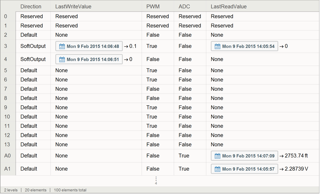
The only properties supported currently are "PinConfigurations", which returns a Dataset of the most recent value of pins as well as the state of various pins; "SerialPort", which returns the name of the serial port the Arduino is attached to; and "ArduinoInstallLocation", which is used for the location of the Arduino software on the host machine.
-
"PinConfigurations" is read only, while "ArduinoInstallLocation" can be used to specify another location to use for compiling and uploading functions.
-
Here is an example:
-
-
"PinConfigurations" and "SerialPort" are read only, while "ArduinoInstallLocation" can be written to and used to specify the location of the Arduino software to use for compiling and uploading functions.
-
The "ArduinoInstallLocation" property specified is verified, so the one specified by the user must be a valid location of the Arduino software. This is determined by the presence of the compiler and uploader utilities as well as other necessary software. All released versions of the Arduino IDE are supported.
Reading Data
-
Possible values for "ReadMode" are "Digital" and "Analog".
-
Reading from an analog pin defaults to performing an analog read of that pin. Reading a digital value can be obtained by using "ReadMode""Digital".
-
Only pins "A0" (14), "A1" (15), "A2" (16), "A3" (17), "A4" (18), and "A5" (19) support analog reading. Any pin supports digital reading.
-
DeviceReadTimeSeries is also supported.
-
"ReturnFunction" f will return f[val]. For analog input pins, val will be a number between 0 and 1023 that corresponds to the analog voltage on that pin. 1023 corresponds to 5 volts, and 0 corresponds to 0 volts. Applying voltages higher than 5 volts to any pin on the Arduino may damage the device. For all other pins, val will be 1 or 0, depending on if the voltage on that pin is above or below 3 volts, respectively.
-
Note: By default, "Arduino" allows any pin to be used interchangeably in read and write mode. DeviceConfigure can be used to configure specific pins as read or write.
DeviceRead[dev,n]
reads the value of pin n.
DeviceRead[dev,{{n1,n2,…}}]
reads the value of each pin ni, returning an association of ni to the pin's value.
DeviceRead[dev,{n,"ReturnFunction"(func)}]
reads the value of pin n, applying func to the value before returning it.
DeviceRead[dev,{n,"ReadMode"mode}]
reads the mode value of pin n.
Writing Data
-
The value val must be either 0 or 1, unless pin n supports Pulse Width Modulation (PWM).
-
DeviceWrite also supports lists of rules.
-
PWM is supported on pins 3, 5, 6, 9, 10, and 11. On these pins, val can be any real number between 0 and 1, or any rational number of the form
 , where
  is an Integer between 0 and 255. This corresponds to the duty cycle of the PWM timer on that pin.
 -
PWM pins also support writing a Quantity of volts between 0 and 5 that is scaled to a duty cycle.
-
Note: By default, "Arduino" allows any pin to be used interchangeably in read and write mode. DeviceConfigure can be used to configure specific pins as read or write.
DeviceWrite[dev,nval]
writes the value val to pin n.
DeviceWrite[dev,<n1val1,n2val2,…>]
writes each value vali to pin ni.
Executing Commands
-
"Scheduling" will schedule the function to be run on the Arduino. This means that the function will continue to be run after the Wolfram Language is closed, as long as the Arduino has uninterrupted power. If the Arduino is reset or loses power, the function will need to be rescheduled.
-
The Arduino can schedule things to millisecond precision, so the time specified by timespec is rounded to the nearest thousandths place.
-
The timing of the schedule specified by timespec supports the following formats:
-
dt runs the function every dt seconds {wait} runs the function once, after waiting wait seconds {dt,count} runs the function count times, every dt seconds -
After scheduling a task on the Arduino, it may be stopped prematurely with DeviceExecute[dev,"DeleteTask",funcname]
-
Note: Only one function may run or be scheduled at any given time on the Arduino.
-
When uploading to the device with DeviceConfigure, specifying "Databin"bin, will configure this function to use bin as the Databin to upload to. If not configured with DeviceConfigure, then the option Databin must be specified, either as a String of the bin's "UUID" or "ShortID", or as the Databin object.
-
Specifying "ReadMode" enables reading the digital value of pin on Analog pins, with "ReadMode""Digital", or else Analog pins will be read as an analog voltage between 0 and 5 volts. "Digital" or Automatic are the only valid values if pin is a digital pin.
-
This function is not available if the device has been configured with "DataDrop"False.
-
Note: Only available on the Arduino Yun.
DeviceExecute[dev,funcname]
executes the function funcname on the Arduino.
DeviceExecute[dev,funcname,args]
executes the function funcname with arguments args on the Arduino.
DeviceExecute[dev,funcname,{args,"Scheduling"timespec}]
executes the function funcname with arguments args on a schedule specified by timespec.
DeviceExecute[dev,DatabinAdd,pin]
on Arduino Yun, uploads the current value of pin to the default Databin specified in DeviceConfigure.
DeviceExecute[dev,DatabinAdd,{pin,"Databin"bin,"Key"name,"ReadMode"mode}]
on Arduino Yun, uploads the current value of pin when read in mode to bin with the Key name.
Closing and Releasing Resources
-
Note that simply physically removing the Arduino from the machine's USB or serial port does not close the connection. DeviceClose is recommended to be called before removal of the device for properly ending usage.
-
Any functions scheduled on the Arduino will continue to run even after the connection to the device is closed, so long as the Arduino has uninterrupted power.
DeviceClose[dev]
closes the connection to the Arduino device dev and frees the serial port.
Examples
Basic Examples (1)
Open a connection to an Arduino and upload the required sketch to the device:
arduino = DeviceOpen["Arduino", "COM3"];Set the Pulse Width Modulation of the duty cycle of pin 3 to be 50%:
DeviceWrite[arduino, 3 -> (128/255)]Write a value of 0 to digital pin 10:
DeviceWrite[arduino, 10 -> 0]Write a Pulse Width Modulation duty cycle to pin 5 that corresponds roughly to 2.5 volts for some devices:
DeviceWrite[arduino, 5 -> Quantity[2.5, "Volts"]]Read from multiple analog input pins:
DeviceRead[arduino, {{"A0", "A1"}}]Read from pin 4, using "ReturnFunction" to compare the value to 1:
DeviceRead[arduino, {4, "ReturnFunction" -> (# === 1&)}]Read the value from analog pin A3, applying a conversion function to turn the value into inches:
DeviceRead[arduino, {"A3", "ReturnFunction" -> (Quantity[# * (1.123/4.7), "Inches"]&)}]Get the most recently read value for a particular pin:
arduino["PinConfigurations"]["A3"]["LastReadValue"]Upload a SymbolicC function to the Arduino that adds two numbers and the number 1000 together:
Needs["SymbolicC`"]DeviceConfigure[arduino, "Upload" -> {"Functions" -> <|"mySymbolicCFunc" -> CFunction["long", "func2", {{"long", "i"}, {"long", "j"}}, CReturn[ COperator[ Plus, {"i", "j", 1000}]]]|>}];Now run the function with the arguments 1 and 20:
DeviceExecute[arduino, "mySymbolicCFunc", {1, 20}]Upload a function to control a servo motor attached to the Arduino on pin 9, taking as its argument the position to rotate the servo to, using the Arduino built-in Servo library:
DeviceConfigure[arduino, "Upload" -> {"Libraries" -> "Servo", Initialization -> "Servo servoMotor;", "Functions" -> <|"ServoRotate" -> <|"ArgumentTypes" -> {Integer}, "ReturnType" -> {}, "Code" -> "
void servoSet(int position)
{
	servoMotor.attach(9);
	servoMotor.write(position);
}"|>|>}];
Now rotate the servo to the 90 degrees position:
DeviceExecute[arduino, "ServoRotate", 90]The following example requires an LCD to be attached to the Arduino on pins 12, 11, 5, 4, 3, and 2. First upload a simple function that writes a string to the LCD screen:
DeviceConfigure[arduino, "Upload" -> {"Libraries" -> "LiquidCrystal", Initialization -> "LiquidCrystal lcd(12,11,5,4,3,2);
void lcdSetup() {pinMode(13,OUTPUT);digitalWrite(13,HIGH);lcd.begin(16,2);}
byte lcdInitQ = 0;", "Functions" -> <|"LCDPrint" -> <|"ArgumentTypes" -> String, "Code" -> "
void lcdWrite(char * str)
{
	if(!lcdInitQ)
	{
		lcdInitQ = 1;
		lcdSetup();
	}
	lcd.clear();
	lcd.print(str);
}"|>|>}];
Now, write a string to the LCD screen:
DeviceExecute[arduino, "LCDPrint", "Arduino+Wolfram"][image]DeviceOpen["Arduino", {"/dev/tty.usbmodem1421", "BoardType" -> "Yun"}]Make a new databin to upload to:
bin = CreateDatabin[]Databin["1qGFQ8v"]Configure the Arduino to use the databin by default:
DeviceConfigure["Arduino", "Upload" -> "Databin" -> bin]"Upload" -> Databin -> Databin["1qGFQ8v"]Upload the current value of the pin "A0" to the bin:
DeviceExecute["Arduino", DatabinAdd, "A0"]Upload the value of the digital pin 4 to the bin once every second for the next ten seconds:
DeviceExecute["Arduino", DatabinAdd, {4, "Scheduling" -> {1, 10}}]Configure the Yun to upload the value of pin "A5" with the key "SensorValue" once every 60 seconds infinitely after starting up:
DeviceConfigure["Arduino", "Upload" -> "BootFunction" -> <|"Code" -> DatabinAdd, "Databin" -> bin, "Pin" -> "A5", "Key" -> "SensorValue", "Scheduling" -> 60|>]