WOLFRAM SYSTEM MODELER
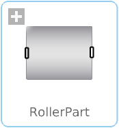
RollerPartClass describing a roller |
|
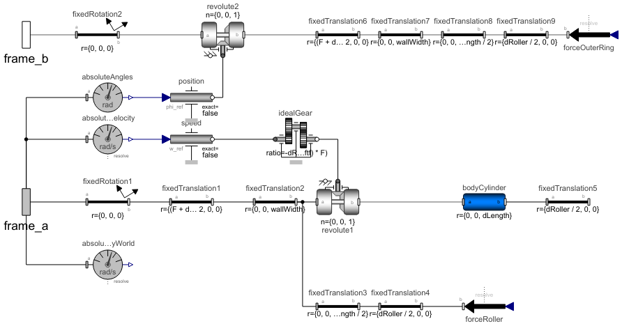
Diagram
Wolfram Language
In[1]:=
SystemModel["RotatingMachinery.RollingBearings.Parts.RollerPart"]
Out[1]:=
Information
Cylindrical Roller Parts
Cylindrical rollers are a type of rolling element used in roller bearings. Compared to ball bearings, roller bearings have a higher load capacity.
The roller in a rolling-element bearing is considered stiff in the sense that the geometry does not change globally, but Hertzian contact is taken into account. The deflection and contact between two cylinders with parallel axes are well documented. As long as the contact surfaces are convex, theoretical solutions exist for both deformation and contact pressure. For concave contact, an approximation called "Contact between a rigid cylinder with flat-ended and an elastic half-space" is used for the deformation, while the contact pressure is theoretically exact [1–2].
Forces
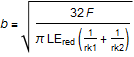
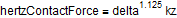
It is assumed that the rollers have contact in the whole roller width, i.e. no crowning. Equation for the Hertz contact width b:
and displacement of cylinders, delta:
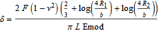
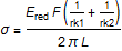
where F is the force, nu is the Poisson ratio, Emod is Young's modulus, L is the length of the cylinder and R is the radius of the cylinder. To simplify the equations, the variable Ered is introduced as:
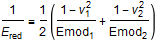
With the preceding equations, delta as a function of the contact force can be solved. However, the simulation time can be improved if the equations are rewritten as shown following. The error in deformation delta is normally less than 1% and in contact stress even better.
The relation between contact force and indentation depth can be written as:

where with good accuracy:
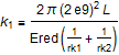
and:
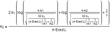
Finally, the load indentation depth constant can be written as:

With the notation used in the source code:
Contact Stress
The Hertz contact stress for a cylinder contact is:
Limitations
For certain types of roller elements, a theoretical solution may not exist, and design optimizations such as crowning may be required to alter their behavior. In such cases, the bearing manufacturer can typically provide information on the nonlinear stiffness and Hertz contact stresses. Alternatively, Finite Element software can be used to determine the relationship between load and roller deformation.
The ideal rotational speed of the roller is explicitly calculated, meaning that friction forces do not drive the rotation of the rollers. However, this limitation is usually only relevant for large bearings when smearing effects must be considered as the roller element moves from an unloaded zone to a loaded zone.
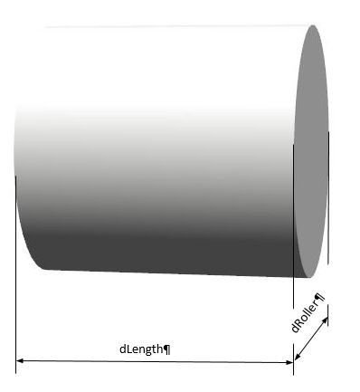
Figure 1: Roller part.
References
[1] Wikipedia. "Contact Mechanics." https://en.wikipedia.org/wiki/Contact_mechanics.
[2] Johnson, K. L. Contact Mechanics. Cambridge University Press, 1985.
Parameters (22)
| d |
Type: Diameter (m) Description: Bearing inner (bore) diameter |
|---|---|
| D |
Type: Diameter (m) Description: Bearing outer diameter |
| B |
Type: Distance (m) Description: Bearing width |
| d1 |
Type: Diameter (m) Description: Bearing innerring wall outer diamter |
| D1 |
Type: Diameter (m) Description: Outer diameter for roller |
| F |
Type: Diameter (m) Description: Inner diameter for roller |
| s |
Type: Distance (m) Description: Cage clearance |
| dRoller |
Type: Diameter (m) Description: Roller diameter |
| dLength |
Type: Distance (m) Description: Roller length |
| wallWidth |
Type: Distance (m) Description: Wall thickness of outer ring |
| angle |
Type: Angle_deg (°) Description: Angle |
| numberOfRollers |
Type: Integer Description: Number of rollers |
| ftf |
Value: F / (2 * F + 2 * dRoller) Type: Real Description: Cage defect frequency (FTF) |
| clearance_z |
Type: Length (m) Description: Clearance in z direction |
| clearance_dr |
Type: Length (m) Description: Clearence in radial direction |
| ny |
Value: 0.3 Type: Real Description: Poisson's ratio |
| Emod |
Value: 210000000000.0 Type: ModulusOfElasticity (Pa) Description: Young's Modulus |
| outerRingDefect |
Value: false Type: Boolean Description: if = true, then an outer ring defect at 12 o´clock is present |
| addForceOuterRingDefectAmplitude |
Value: 0 Type: Force (N) Description: Magnutude of outer ring defect force. Only valid if outerRingDefect = true |
| animateRollers |
Value: true Type: Boolean Description: Animate rollers |
| animateRollerForce |
Value: true Type: Boolean Description: Animate roller forces |
| animateOuterRingForce |
Value: false Type: Boolean Description: Animate outer ring forces |
Connectors (2)
Components (23)
| forceRoller |
Type: WorldForce Description: External force acting at frame_b, defined by 3 input signals and resolved in frame world, frame_b or frame_resolve |
|
|---|---|---|
| forceOuterRing |
Type: WorldForce Description: External force acting at frame_b, defined by 3 input signals and resolved in frame world, frame_b or frame_resolve |
|
| absoluteAngles |
Type: AbsoluteAngles Description: Measure absolute angles between frame connector and the world frame |
|
| revolute1 |
Type: Revolute Description: Revolute joint (1 rotational degree-of-freedom, 2 potential states, optional axis flange) |
|
| idealGear |
Type: IdealGear Description: Ideal gear without inertia |
|
| absoluteAngularVelocity |
Type: AbsoluteAngularVelocity Description: Measure absolute angular velocity of frame connector |
|
| speed |
Type: Speed Description: Forced movement of a flange according to a reference angular velocity signal |
|
| absoluteAngularVelocityWorld |
Type: AbsoluteAngularVelocity Description: Measure absolute angular velocity of frame connector |
|
| revolute2 |
Type: Revolute Description: Revolute joint (1 rotational degree-of-freedom, 2 potential states, optional axis flange) |
|
| position |
Type: Position Description: Forced movement of a flange according to a reference angle signal |
|
| bodyCylinder |
Type: BodyCylinder Description: Rigid body with cylinder shape. Mass and animation properties are computed from cylinder data and density (12 potential states) |
|
| world |
Type: World Description: World coordinate system + gravity field + default animation definition |
|
| fixedRotation1 |
Type: FixedRotation Description: Fixed translation followed by a fixed rotation of frame_b with respect to frame_a |
|
| fixedTranslation1 |
Type: FixedTranslation Description: Fixed translation of frame_b with respect to frame_a |
|
| fixedTranslation2 |
Type: FixedTranslation Description: Fixed translation of frame_b with respect to frame_a |
|
| fixedTranslation3 |
Type: FixedTranslation Description: Fixed translation of frame_b with respect to frame_a |
|
| fixedTranslation4 |
Type: FixedTranslation Description: Fixed translation of frame_b with respect to frame_a |
|
| fixedTranslation5 |
Type: FixedTranslation Description: Fixed translation of frame_b with respect to frame_a |
|
| fixedRotation2 |
Type: FixedRotation Description: Fixed translation followed by a fixed rotation of frame_b with respect to frame_a |
|
| fixedTranslation6 |
Type: FixedTranslation Description: Fixed translation of frame_b with respect to frame_a |
|
| fixedTranslation7 |
Type: FixedTranslation Description: Fixed translation of frame_b with respect to frame_a |
|
| fixedTranslation8 |
Type: FixedTranslation Description: Fixed translation of frame_b with respect to frame_a |
|
| fixedTranslation9 |
Type: FixedTranslation Description: Fixed translation of frame_b with respect to frame_a |
Used in Components (1)
|
RotatingMachinery.RollingBearings.Parts Model of an assembly of rollers, containing RollerPart components |