
BezierSurface
BezierSurface[{{p1,p2,…},…}]
制御点 piによって定義されたベジエ(Bézier)曲面を表す.
詳細とオプション
- BezierSurfaceはベジエパッチとしても知られている.
- BezierSurfaceは,一般に,コンピュータ支援設計(CAD)およびコンピュータグラフィックスにおいて,自由形状の曲面をモデル化するために用いられる.
- 制御点 piは {x,y,z}のような通常の三次元座標である.
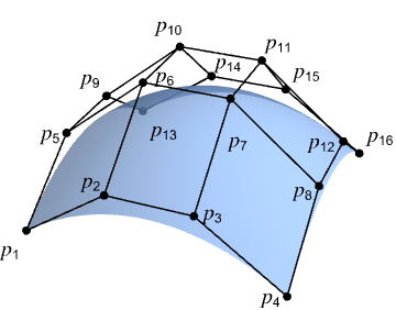
- BezierSurface[{{p1,p2,p3,p4},…,{p13,p14,p15,p16}}]は,点の4×4配列 p1,p2,…,p16を持つ双三次ベジエ曲面を表す.
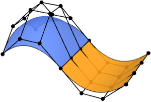
- 4×4を超える制御点を持つBezierSurfaceは,合成三次ベジエ曲面を表す.
- 合成曲面は,複数のベジエパッチを用いて複雑な幾何形状がモデル化できる.
- BezierSurfaceは,幾何領域およびグラフィックスプリミティブとして使用できる.
- グラフィックスでは,点 pi は,Scaled式またはDynamic式でよい.
- グラフィックスの描画は,FaceForm,EdgeForm,Texture,Specularity,Opacity等の指示子および色の影響を受ける.
- FaceForm[front,back]を使って,3Dの曲目の表と裏に異なるスタイルが指定できる.
- 次は,使用可能なオプションである.
-
SplineDegree Automatic 多項式基底の次数 SplineClosed False 表面を閉じたものにするかどうか - オプションSplineDegree->d は,各方向に最大次数 d を指定する.SplineDegree->{d1,d2}は,曲面内の2方向に異なる最大次数を指定する.
- SplineDegree->{d1,d2}のとき,(d1+1)×(d2+1)個の制御点を持つBezierSurfaceは,次数がそれぞれ d1 および d2 である単純なベジエ曲面を与える.制御点が少ない場合には,より低次数の曲面が生成され,制御点が多い場合には,合成ベジエ曲面が生成される.

例題
すべて開く すべて閉じる例 (3)
Graphics3D[BezierSurface[{{{0, 0, 0}, {0, 4, 4}, {0, 8, 3}}, {{4, 0, 4}, {4, 4, 0}, {4, 8, 0}}, {{8, 0, 1}, {8, 4, 0}, {8, 8, 3}}}]]reg = BezierSurface[IconizedObject[«[image]»]];Area[reg]RegionBounds[reg]Graphics3D[{MaterialShading["Pewter"], BezierSurface[IconizedObject[«[image]»]]}, ...]スコープ (26)
基本的な用法 (5)
Graphics3D[BezierSurface[{{{0, 0, 0}, {2, 0, 0}}, {{0, 1, 0}, {2, 1, 0}}}]]Graphics3D[BezierSurface[IconizedObject[«[image]»]]]Graphics3D[BezierSurface[IconizedObject[«[image]»]]]Graphics3D[BezierSurface[IconizedObject[«[image]»], SplineClosed -> {False, True}]]Graphics3D[BezierSurface[IconizedObject[«[image]»], SplineClosed -> {False, True}]]Graphics3D[BezierSurface[IconizedObject[«[image]»], SplineClosed -> {True, True}]]Graphics3D[BezierSurface[IconizedObject[«[image]»], SplineClosed -> {False, True}]]Graphics3D /@ {BezierSurface[IconizedObject[«[image]»], SplineClosed -> {True, False}], BezierSurface[IconizedObject[«[image]»], SplineClosed -> {True, False}]}BezierSurfaceは,位相円板を表すことができる:
Graphics3D[BezierSurface[IconizedObject[«[image]»]]]Graphics3D[BezierSurface[IconizedObject[«[image]»], SplineClosed -> {True, False}]]Graphics3D[BezierSurface[IconizedObject[«[image]»], SplineClosed -> {False, True}]]Graphics3D[BezierSurface[IconizedObject[«[image]»], SplineClosed -> True]]BezierSurface[{{{0, 0, 0}, {0, 4, 4}, {0, 8, 3}}, {{4, 0, 4}, {4, 4, 0}, {4, 8, 0}}, {{8, 0, 1}, {8, 4, 0}, {8, 8, 3}}}]指定 (3)
Graphics3D[BezierSurface[(| | | |
| --------- | --------- | --------- |
| {0, 0, 0} | {0, 4, 4} | {0, 8, 3} |
| {4, 0, 4} | {4, 4, 0} | {4, 8, 0} |
| {8, 0, 1} | {8, 4, 0} | {8, 8, 3} |)]]Graphics3D[BezierSurface[(| | | | |
| --------- | --------- | --------- | --------- |
| {0, 0, 0} | {3, 0, 2} | {5, 0, 2} | {8, 0, 1} |
| {0, 3, 2} | {3, 3, 2} | {5, 3, 1} | {8, 3, 1} |
| {0, 5, 3} | {3, 5, 2} | {5, 5, 1} | {8, 5, 1} |
| {0, 8, 3} | {3, 8, 2} | {5, 8, 2} | {8, 8, 3} |)]]一般に,次数が d の単純なベジエパッチには制御点の(d-1)×(d-1)配列が必要である:
pts = (| | | | | |
| --------- | --------- | --------- | --------- | --------- |
| {0, 0, 0} | {1, 0, 1} | {2, 0, 0} | {3, 0, 1} | {4, 0, 0} |
| {0, 1, 1} | {1, 1, 2} | {2, 1, 1} | {3, 1, 2} | {4, 1, 1} |
| {0, 2, 0} | {1, 2, 1} | {2, 2, 0} | {3, 2, 1} | {4, 2, 0} |
| {0, 3, 1} | {1, 3, 2} | {2, 3, 1} | {3, 3, 2} | {4, 3, 1} |
| {0, 4, 0} | {1, 4, 1} | {2, 4, 0} | {3, 4, 1} | {4, 4, 0} |);deg = Take[Dimensions[pts], 2] - 1;BezierSurface[pts, SplineDegree -> deg]Graphics3D[%]BezierSurface[Take[pts, 1 ;; 3, 1 ;; 3], SplineDegree -> deg]Graphics3D[%]BezierSurface[pts, SplineDegree -> 2]Graphics3D[%]Graphics3D[{BezierSurface[IconizedObject[«[image]»]]}]Graphics3D[{BezierSurface[IconizedObject[«[image]»], SplineClosed -> True]}]Graphics3D[{BezierSurface[IconizedObject[«[image]»], SplineClosed -> #]}]& /@ {{True, False}, {False, True}}グラフィックス (12)
Table[Graphics3D[{c, BezierSurface[IconizedObject[«[image]»]]}], {c, {RGBColor[0.93, 0.27, 0.27], RGBColor[0.14, 0.8, 0.14], RGBColor[0.4, 0.6, 1]}}]FaceFormを使って曲面と表と裏に異なる特性が指定できる:
Graphics3D[{FaceForm[RGBColor[0.93, 0.27, 0.27], RGBColor[0.14, 0.8, 0.14]], BezierSurface[IconizedObject[«[image]»]]}]EdgeFormを使って曲面の境界辺のスタイルが指定できる:
Graphics3D[{EdgeForm[{Red, Thick, Dashed}], BezierSurface[IconizedObject[«[image]»]]}]Table[Graphics3D[{EdgeForm[{StandardYellow, Thick}], BezierSurface[IconizedObject[«[image]»], SplineClosed -> closed]}, Lighting -> "Accent"], {closed, {False, True}}]Table[Graphics3D[{Black, Specularity[White, n], BezierSurface[IconizedObject[«[image]»]]}, Lighting -> "Accent"], {n, {5, 20, 100}}]Opacityは面の不透明度を指定する:
Table[Graphics3D[{Opacity[o], BezierSurface[IconizedObject[«[image]»]]}], {o, {0.1, 0.5, 0.9}}]Glowは,Lightingとは無関係に,表面の色を指定する:
Table[Graphics3D[{Glow[c], BezierSurface[IconizedObject[«[image]»]]}, Lighting -> None], {c, {RGBColor[0.93, 0.27, 0.27], RGBColor[0.14, 0.8, 0.14], RGBColor[0.4, 0.6, 1]}}]これをLightingと一緒に使って微妙な陰影を作成する:
Table[Graphics3D[{Glow[glow], GrayLevel[0.4], BezierSurface[IconizedObject[«[image]»]]}, Lighting -> "Accent"], {glow, {RGBColor[0.93, 0.27, 0.27], RGBColor[0.14, 0.8, 0.14], RGBColor[0.4, 0.6, 1]}}]Textureを曲面に適用する:
Graphics3D[{Texture[[image]], BezierSurface[IconizedObject[«[image]»]]}, Lighting -> "Neutral"]Table[Graphics3D[{s, BezierSurface[IconizedObject[«[image]»]]}, Lighting -> "Accent"], {s, {StippleShading[0.6], ToonShading[Red], GoochShading[]}}]MaterialShadingを使って物理ベースの材料で曲面を描画する:
Table[Graphics3D[{MaterialShading[mat], BezierSurface[IconizedObject[«[image]»]]}, Lighting -> "ThreePoint"], {mat, {"Gold", "Satin", "Velvet"}}]BezierSurfaceはGraphicsComplexで使うことができる:
Graphics3D[{GraphicsComplex[{{0, 0, 0}, {0, 10, 12}, {0, 20, 9}, {10, 0, 12}, {10, 10, 0}, {10, 20, 0}, {20, 0, 3}, {20, 10, 0}, {20, 20, 9}}, BezierSurface[{{1, 2, 3}, {4, 5, 6}, {7, 8, 9}}]]}]pts = IconizedObject[«[image]»];Table[Graphics3D[{BezierSurface[pts]}, PlotRange -> {{0, pr}, {0, pr}, {0, pr}}], {pr, {1, 2, 4}}]Scaledを使って制御点をPlotRangeと相対的に指定する:
scaled = Map[Scaled, pts, {2}];Table[Graphics3D[{BezierSurface[scaled]}, PlotRange -> {{0, pr}, {0, pr}, {0, pr}}], {pr, {1, 2, 4}}]座標はDynamicでもよい:
DynamicModule[{z = 0, pts},
	pts = {{Dynamic[{0, 0, z}], {0, 4, 4}, {0, 8, 3}}, {{4, 0, 4}, {4, 4, 0}, {4, 8, 0}}, {{8, 0, 1}, {8, 4, 0}, {8, 8, 3}}};
	{Slider[Dynamic[z], {0, 4}], Graphics3D[{BezierSurface[pts]}]}]
領域 (6)
reg = BezierSurface[{{{Indexed[a, {1}], Indexed[a, {2}], Indexed[a, {3}]}, {Indexed[a, {4}], Indexed[a, {5}], Indexed[a, {6}]}, {Indexed[a, {7}], Indexed[a, {8}], Indexed[a, {9}]}}, {{Indexed[b, {1}], Indexed[b, {2}], Indexed[b, {3}]}, {Indexed[b, {4}], Indexed[b, {5}], Indexed[b, {6}]}, {Indexed[b, {7}], Indexed[b, {8}], Indexed[b, {9}]}}, {{Indexed[c, {1}], Indexed[c, {2}], Indexed[c, {3}]}, {Indexed[c, {4}], Indexed[c, {5}], Indexed[c, {6}]}, {Indexed[c, {7}], Indexed[c, {8}], Indexed[c, {9}]}}}];RegionEmbeddingDimension[reg]RegionDimension[reg]reg = BezierSurface[{{{0, 0, 0}, {0, 4, 4}, {0, 8, 3}}, {{4, 0, 4}, {4, 4, 0}, {4, 8, 0}}, {{8, 0, 1}, {8, 4, 0}, {8, 8, 3}}}];{RegionMember[reg, {0, 0, 0}], RegionMember[reg, {1, 2, 3}]}reg = BezierSurface[{{{0, 0, 0}, {0, 4, 4}, {0, 8, 3}}, {{4, 0, 4}, {4, 4, 0}, {4, 8, 0}}, {{8, 0, 1}, {8, 4, 0}, {8, 8, 3}}}];{Area[reg], RegionMeasure[reg]}c = RegionCentroid[reg]Show[Region[reg], Graphics3D[{Black, Point[c]}]]reg = BezierSurface[{{{0, 0, 0}, {0, 4, 4}, {0, 8, 3}}, {{4, 0, 4}, {4, 4, 0}, {4, 8, 0}}, {{8, 0, 1}, {8, 4, 0}, {8, 8, 3}}}];{RegionDistance[reg, {0, 0, 0}], RegionDistance[reg, {1, 1, 0}]}Show[Region[reg], ContourPlot3D[Evaluate@RegionDistance[reg, {x, y, z}], {x, 0, 8}, {y, 0, 8}, {z, -4, 8}, Contours -> {1, 2, 3, 4}, ...], Boxed -> True, Axes -> True]reg = BezierSurface[{{{0, 0, 0}, {0, 4, 4}, {0, 8, 3}}, {{4, 0, 4}, {4, 4, 0}, {4, 8, 0}}, {{8, 0, 1}, {8, 4, 0}, {8, 8, 3}}}];{SignedRegionDistance[reg, {0, 0, 0}], SignedRegionDistance[reg, {1, 1, 0}]}reg = BezierSurface[{{{0, 0, 0}, {0, 4, 4}, {0, 8, 3}}, {{4, 0, 4}, {4, 4, 0}, {4, 8, 0}}, {{8, 0, 1}, {8, 4, 0}, {8, 8, 3}}}];BoundedRegionQ[reg]bb = CoordinateBoundingBox[reg]Show[Region[reg], Graphics3D[{Opacity[0.1], EdgeForm[Dashed], AmbientLight[White], Cuboid@@bb}]]オプション (5)
SplineDegree (3)
デフォルトで,4×4個以上の制御点があるBezierSurfaceは次数3を使う:
pts = Table[{i, j, (-1) ^ (i * j)}, {i, 7}, {j, 7}];{BezierSurface[Take[pts, 4, 4]], BezierSurface[Take[pts, 7, 7]]}{BezierSurface[Take[pts, 2, 2]], BezierSurface[Take[pts, 3, 3]]}SplineDegreeを使ってより低い次数を使うように指定する:
BezierSurface[pts, SplineDegree -> 1]BezierSurface[pts, SplineDegree -> 6]n×n 個の制御点があるBezierSurfaceについて次数 d を指定する.ここで,d<n-1のときは合成ベジエ曲面が与えられる:
pts = Table[{i, j, (-1) ^ (i * j)}, {i, 9}, {j, 9}];Region[BezierSurface[pts, SplineDegree -> #]]& /@ {2, 4, 8}pts = Table[{i, j, (-1) ^ (i * j)}, {i, 9}, {j, 9}];Region[BezierSurface[pts, SplineDegree -> #]]& /@ {2, {2, 8}, {8, 2}}SplineClosed (2)
pts = IconizedObject[«[image]»];Graphics3D[{BezierSurface[pts]}]Graphics3D /@ {BezierSurface[pts, SplineClosed -> {True, False}], BezierSurface[pts, SplineClosed -> {False, True}]}Graphics3D[{BezierSurface[pts, SplineClosed -> True]}]制御点配列の第1行/列を配列の最後にコピーすることで境界は閉じられる:
pts = IconizedObject[«[image]»];Graphics3D[{BezierSurface[pts, SplineDegree -> 10]}]Graphics3D /@ {
BezierSurface[Append[pts, First[pts]], SplineDegree -> 10], BezierSurface[pts, SplineDegree -> 10, SplineClosed -> {True, False}]
}アプリケーション (4)
基本的なアプリケーション (1)
composite = BezierSurface[IconizedObject[«[image]»], SplineClosed -> {True, False}];composite//Regiondecompose[reg : BezierSurface[cpts_, ___]] := Block[...]Graphics3D[{Table[{RandomColor[Hue[_, 0.7, 1]], surface}, {surface, decompose[composite]}]}, ...]モデリング (3)
pts = IconizedObject[«[image]»];Graphics3D[{Map[Line, Join[pts, Transpose[pts]]], Point[Join@@pts]}, Boxed -> False]ケージ上に滑らかなBezierSurfaceを定義する:
surface = BezierSurface[IconizedObject[«[image]»], SplineClosed -> {True, False}]Graphics3D[{MaterialShading["Gold"], surface}, ...]合成BezierSurfaceを使って鋭い辺を持つオブジェクトをモデル化する:
Graphics3D[{MaterialShading["Glazed"], BezierSurface[IconizedObject[«[image]»], SplineClosed -> {False, True}]}, ...]Graphics3D[{MaterialShading["Pewter"], BezierSurface[IconizedObject[«[image]»], SplineClosed -> {True, False}]}, ...]特性と関係 (11)
次数1の単純なBezierSurfaceはPolygonに等しい:
pts = {{{0, 0, 1}, {2, 0, 0}}, {{0, 2, 2}, {2, 2, 1}}};Graphics3D /@ {BezierSurface[pts], Polygon[Join[First[pts], Reverse[Last[pts]]]]}BezierSurfaceはBSplineSurfaceの特殊ケースである:
Graphics3D /@ {BezierSurface[IconizedObject[«[image]»]], BSplineSurface[IconizedObject[«[image]»]]}次数 d のベジエパッチから構成される合成BezierSurfaceは,次数 d の単一のBSplineSurfaceと,特定のSplineKnotsの選択によって表現できる:
knots = {{0, 0, 0, 0, 1, 1, 1, 2, 2, 2, 2}, {0, 0, 0, 0, 1, 1, 1, 2, 2, 2, 2}};Graphics3D /@ {BezierSurface[IconizedObject[«[image]»]], BSplineSurface[IconizedObject[«[image]»], SplineKnots -> knots]}RegionConvertを使って任意のBezierSurfaceを同等のBSplineSurfaceに変換する:
bezier = BezierSurface[IconizedObject[«[image]»]];
bspline = RegionConvert[bezier, "Spline"];Graphics3D /@ {bezier, bspline}BezierCurveは制御点のリストを取るBezierSurfaceの低次元形式である:
pts = {{-3, 0}, {6, 5}, {-6, -5}, {3, 0}};Graphics[BezierCurve[pts]]BezierSurfaceの境界辺は4本のベジエ曲線によって形成される:
pts = IconizedObject[«[image]»];bc = Map[BezierCurve, {pts[[1]], pts[[-1]], pts[[All, 1]], pts[[All, -1]]}];Graphics3D[{BezierSurface[pts], Thick, StandardRed, bc}]BezierSurface上のすべての等パラメトリック曲線は,有効なベジエ曲線である:
uc = Table[BezierCurve[Map[#[u]&, Map[BezierFunction, pts]]], {u, 0, 1, 1 / 5}];
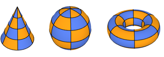
vc = Table[BezierCurve[Map[#[v]&, Map[BezierFunction, Transpose[pts]]]], {v, 0, 1, 1 / 5}];Graphics3D[{BezierSurface[pts], Thick, RGBColor[0.14, 0.8, 0.14], uc, RGBColor[0.4, 0.6, 1], vc}]合成BezierSurfaceは,Sphere,Torus,Coneのようなプリミティブの近似に使うことができる:
Graphics3D /@ {Torus[], Sphere[], Cone[]}Graphics3D /@ {BezierSurface[...], BezierSurface[...], BezierSurface[...]}BezierSurfaceは,角にある4つの制御点を常に補間する:
pts = IconizedObject[«[image]»];
corners = {pts[[1, 1]], pts[[-1, 1]], pts[[-1, -1]], pts[[1, -1]]};RegionMember[BezierSurface[pts], corners]Graphics3D[{BezierSurface[pts], Red, PointSize[Medium], Point[corners]}]opts = Complement[Join@@pts, corners];RegionMember[BezierSurface[pts], opts]//Countspts = IconizedObject[«[image]»];Show[Region[BezierSurface[pts]], Graphics3D[{Opacity[0.1], EdgeForm[Directive[Dashed]], ConvexHullRegion[Join@@pts]}]]BezierFunctionは,2つのパラメータの特定の値に対応するBezierSurface上の位置を与える:
pts = IconizedObject[«[image]»];bfunc = BezierFunction[pts]positions = Join@@Table[bfunc[u, v], {u, 0, 1, 1 / 10}, {v, 0, 1, 1 / 10}];Graphics3D[{BezierSurface[pts], StandardRed, PointSize[0.02], Point[positions]}]ベジエ曲面は,ベルンシュタイン多項式を用いてその制御点の重み付き和を取ることによって構成できる:
pts = IconizedObject[«[image]»];bezier[u_, v_] := Sum[BernsteinBasis[3, j, v] * BernsteinBasis[3, i, u] * pts[[i + 1, j + 1]], {i, 0, 3}, {j, 0, 3}]GraphicsRow[{ParametricPlot3D[bezier[u, v], {u, 0, 1}, {v, 0, 1}], Graphics3D[BezierSurface[pts], Axes -> True]}, ImageSize -> Medium]pts = IconizedObject[«[image]»];A = AffineTransform[{(| | | |
| -- | - | - |
| 0 | 1 | 0 |
| -1 | 0 | 0 |
| 0 | 0 | 2 |), {1, 2, 3}}];Graphics3D[#, Axes -> True]& /@ {GeometricTransformation[BezierSurface[pts], A], BezierSurface[A[pts]]}デフォルトでは,合成ベジエ曲面は,2つのパッチ間の継ぎ目に沿って滑らかではない:
pts = IconizedObject[«[image]»];Graphics3D[{BezierSurface[pts, SplineDegree -> 4], {Map[Point, pts], Line[pts], Line[Transpose[pts]]}}]滑らかな継ぎ目を保証するため,継ぎ目をまたぐ点を共線に設定する:
pts[[4, All, 3]] = pts[[5, All, 3]];
pts[[6, All, 3]] = pts[[5, All, 3]];Graphics3D[{BezierSurface[pts, SplineDegree -> 4], {Map[Point, pts], Line[pts], Line[Transpose[pts]]}}]SubdivisionRegionは,制御パッチではなく制御メッシュから滑らかな曲面を生成する:
Graphics3D /@ {SubdivisionRegion[[image]], BezierSurface[IconizedObject[«[image]»]]}インタラクティブな例題 (2)
De Casteljauのアルゴリズムは,ベジエ曲線上の点を生成するために再帰的な線形補間を実行する:
Manipulate[
	DynamicModule[{pts = {...}},
	Graphics[{{Thick, LightGray, BezierCurve[pts]}, {StandardOrange, PointSize[Medium], casteljau[pts, u]}, PointSize[Large], Point[BezierFunction[pts][u]]}]
	], {u, 0, 1}, Initialization :> {...}
]Manipulate[
DynamicModule[{pts = {...}, prims},
prims = casteljau[pts, uv[[2]], uv[[1]]];
Graphics3D[{Map[Line, Join[pts, Transpose[pts]]], {Opacity[0.8], BezierSurface[pts]}, Thickness[0.005], PointSize[0.02], RGBColor[0.4, 0.6, 1], prims[[1]], RGBColor[0.98, 0.56, 0.17], prims[[2]], LightDarkSwitched[GrayLevel[0], GrayLevel[1]], Ball[BezierFunction[pts]@@uv, Scaled[0.02]]}, Boxed -> False, Lighting -> "ThreePoint"]
], {{uv, {0.5, 0.5}}, {0, 0}, {1, 1}}, ControlPlacement -> Left,
Initialization :> {...}
]Manipulate[
DynamicModule[{pts},
pts = unrolledTorusControlPoints[t, {21, 10}, 5, 10, 7];
Graphics3D[{EdgeForm[Thick], BezierSurface[pts]}, ...]
], {t, 0, 1}, Initialization :> {...}
]テキスト
Wolfram Research (2026), BezierSurface, Wolfram言語関数, https://reference.wolfram.com/language/ref/BezierSurface.html.
CMS
Wolfram Language. 2026. "BezierSurface." Wolfram Language & System Documentation Center. Wolfram Research. https://reference.wolfram.com/language/ref/BezierSurface.html.
APA
Wolfram Language. (2026). BezierSurface. Wolfram Language & System Documentation Center. Retrieved from https://reference.wolfram.com/language/ref/BezierSurface.html