WOLFRAM SYSTEM MODELER
CutForceAndTorqueMeasure cut force vector and cut torque |
|
Diagram
Wolfram Language
In[1]:=
SystemModel["PlanarMechanics.Sensors.CutForceAndTorque"]
Out[1]:=
Information
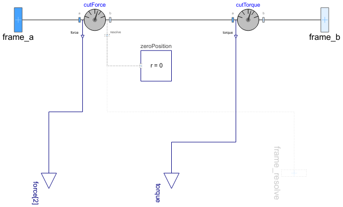
The cut-force and cut-torque acting between the two frames to which this
model is connected, are determined and provided at the output signal connectors
force (= frame_a.f) and torque
(= frame_a.t).
If parameter positiveSign = false, the negative
cut-force and cut-torque is provided (= frame_b.f, frame_b.t).
Via parameter resolveInFrame it is defined, in which frame
the force vector is resolved.
| resolveInFrame = … | Force vector resolved in |
|---|---|
| Types.ResolveInFrameAB.world | world frame |
| Types.ResolveInFrameAB.frame_a | frame_a |
| Types.ResolveInFrameAB.frame_b | frame_b |
| Types.ResolveInFrameAB.frame_resolve | frame_resolve (must be connected) |
If resolveInFrame = Types.ResolveInFrameAB.frame_resolve,
the conditional connector frame_resolve is enabled and
output force is resolved in the frame, to which
frame_resolve is connected.
Note, if this connector is enabled, it must be connected.
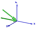
In the following figure the animation of the
sensor is shown. The dark blue coordinate system is frame_b,
and the green arrows are the cut force and the cut torque,
respectively, acting at frame_b and
with negative sign at frame_a.
Parameters (3)
| animation |
Value: true Type: Boolean Description: = true, if animation shall be enabled (show force and torque arrow) |
|---|---|
| positiveSign |
Value: true Type: Boolean Description: = true, if force and torque with positive sign is returned (= frame_a.f/.t), otherwise with negative sign (= frame_b.f/.t) |
| resolveInFrame |
Value: Modelica.Mechanics.MultiBody.Types.ResolveInFrameA.frame_a Type: ResolveInFrameA Description: Frame in which output vector(s) is/are resolved (1: world, 2: frame_a, 3: frame_resolve) |
Inputs (7)
| N_to_m |
Default Value: planarWorld.defaultN_to_m Type: Real (N/m) Description: Force arrow scaling (length = force/N_to_m) |
|---|---|
| Nm_to_m |
Default Value: planarWorld.defaultNm_to_m Type: Real (N⋅m/m) Description: Torque arrow scaling (length = torque/Nm_to_m) |
| forceDiameter |
Default Value: planarWorld.defaultArrowDiameter Type: Diameter (m) Description: Has no longer an effect and is only kept for backwards compatibility (arrow visualization by Vector now) |
| torqueDiameter |
Default Value: forceDiameter Type: Diameter (m) Description: Has no longer an effect and is only kept for backwards compatibility (arrow visualization by Vector now) |
| forceColor |
Default Value: Modelica.Mechanics.MultiBody.Types.Defaults.ForceColor Type: Color Description: Color of force arrow |
| torqueColor |
Default Value: Modelica.Mechanics.MultiBody.Types.Defaults.TorqueColor Type: Color Description: Color of torque arrow |
| specularCoefficient |
Default Value: planarWorld.defaultSpecularCoefficient Type: SpecularCoefficient Description: Reflection of ambient light (= 0: light is completely absorbed) |
Connectors (5)
| frame_a |
Type: Frame_a Description: Coordinate system a |
|
|---|---|---|
| frame_b |
Type: Frame_b Description: Coordinate system b |
|
| frame_resolve |
Type: Frame_resolve Description: Output vectors are optionally resolved in this frame (cut-force/-torque are set to zero) |
|
| force |
Type: RealOutput[2] Description: Cut force resolved in frame defined by resolveInFrame |
|
| torque |
Type: RealOutput Description: Cut torque resolved in frame defined by resolveInFrame |
Components (6)
| planarWorld |
Type: PlanarWorld Description: Planar world coordinate system + gravity field + default animation definition |
|
|---|---|---|
| arrowForce |
Type: Vector Description: Visualizing a vector quantity (force, torque, etc.) |
|
| arrowTorque |
Type: Vector Description: Visualizing a vector quantity (force, torque, etc.) |
|
| cutForce |
Type: BasicCutForce Description: Measure cut force vector (frame_resolve must be connected) |
|
| cutTorque |
Type: BasicCutTorque Description: Measure cut-torque vector |
|
| zeroPosition |
Type: ZeroPosition Description: Set zero position vector and orientation object of frame_resolve |
Revisions
 Developed 2010 at the DLR Institute of System Dynamics and Control