WOLFRAM SYSTEM MODELER
TorqueTorque acting between two frames, defined by 3 input signals and resolved in frame world, frame_a, frame_b or frame_resolve |
|
Diagram
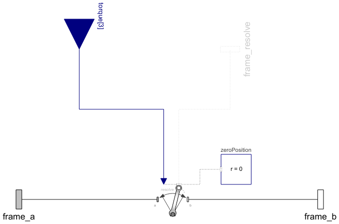
Wolfram Language
In[1]:=
SystemModel["Modelica.Mechanics.MultiBody.Forces.Torque"]
Out[1]:=

Information
This information is part of the Modelica Standard Library maintained by the Modelica Association.
The 3 signals of the torque connector are interpreted as the x-, y- and z-coordinates of a torque acting at the frame connector to which frame_b of this component is attached. Via parameter resolveInFrame it is defined, in which frame these coordinates shall be resolved:
| Types.ResolveInFrameAB. | Meaning |
|---|---|
| world | Resolve input torque in world frame |
| frame_a | Resolve input torque in frame_a |
| frame_b | Resolve input torque in frame_b (= default) |
| frame_resolve | Resolve input torque in frame_resolve (frame_resolve must be connected) |
If resolveInFrame = ResolveInFrameAB.frame_resolve, the torque coordinates are with respect to the frame, that is connected to frame_resolve.
If torque={100,0,0}, and for all parameters the default setting is used, then the interpretation is that a torque of 100 N.m is acting along the positive x-axis of frame_b.
Note, the cut-forces in frame_a and frame_b (frame_a.f, frame_b.f) are always set to zero and the cut-torque at frame_a (frame_a.t) is the same as the cut-torque at frame_b (frame_b.t) but with opposite sign.
An example how to use this model is given in the following figure:

This leads to the following animation (the yellow cylinder characterizes the line between frame_a and frame_b of the Torque component, i.e., the torque acts with negative sign also on the opposite side of this cylinder, but for clarity this is not shown in the animation):

Parameters (2)
| animation |
Value: true Type: Boolean Description: = true, if animation shall be enabled |
|---|---|
| resolveInFrame |
Value: Modelica.Mechanics.MultiBody.Types.ResolveInFrameAB.frame_b Type: ResolveInFrameAB Description: Frame in which input force is resolved (1: world, 2: frame_a, 3: frame_b, 4: frame_resolve) |
Inputs (4)
| connectionLineDiameter |
Default Value: world.defaultArrowDiameter Type: Diameter (m) Description: Diameter of line connecting frame_a and frame_b |
|---|---|
| torqueColor |
Default Value: Modelica.Mechanics.MultiBody.Types.Defaults.TorqueColor Type: Color Description: Color of torque arrow |
| connectionLineColor |
Default Value: Modelica.Mechanics.MultiBody.Types.Defaults.SensorColor Type: Color Description: Color of line connecting frame_a and frame_b |
| specularCoefficient |
Default Value: world.defaultSpecularCoefficient Type: SpecularCoefficient Description: Reflection of ambient light (= 0: light is completely absorbed) |
Connectors (4)
| frame_a |
Type: Frame_a Description: Coordinate system a fixed to the component with one cut-force and cut-torque |
|
|---|---|---|
| frame_b |
Type: Frame_b Description: Coordinate system b fixed to the component with one cut-force and cut-torque |
|
| frame_resolve |
Type: Frame_resolve Description: The input signals are optionally resolved in this frame |
|
| torque |
Type: RealInput[3] Description: x-, y-, z-coordinates of torque resolved in frame defined by resolveInFrame |
Components (5)
| world |
Type: World Description: World coordinate system + gravity field + default animation definition |
|
|---|---|---|
| torqueArrow |
Type: Vector Description: Visualizing a vector quantity (force, torque, etc.) |
|
| connectionLine |
Type: Shape Description: Visualizing an elementary object with variable size; all data have to be set as modifiers (see info layer) |
|
| basicTorque |
Type: BasicTorque Description: Torque acting between two frames, defined by 3 input signals |
|
| zeroPosition |
Type: ZeroPosition Description: Set absolute position vector of frame_resolve to a zero vector and the orientation object to a null rotation |
Used in Examples (3)
|
Modelica.Mechanics.MultiBody.Examples.Rotational3DEffects Demonstrates usage of models Rotor1D and Mounting1D |
|
|
Modelica.Mechanics.MultiBody.Examples.Rotational3DEffects Demonstrates usage of model Rotor1D mounted on a moving body |
|
|
Modelica.Mechanics.MultiBody.Examples.Rotational3DEffects Demonstrate usage of GearConstraint model |