BoundaryMeshRegion[{p1,p2,…},{bcell1[{i1,…}],bcell2[{j1,…}],…}]
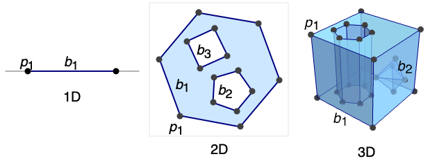
境界セル bcelljを持つメッシュを与える.ただし,整数 i として与えられた座標は piとみなされ,セル全体で閉じた曲線,曲面等を表す.
BoundaryMeshRegion[…,{…,wi[bcelli[…]],…}]
セルの特性が記号ラッパー wiで定義されたメッシュを与える.
BoundaryMeshRegion[…,boundary1,boundary2,…]
複数の境界 boundaryiからメッシュを与える.
BoundaryMeshRegion
BoundaryMeshRegion[{p1,p2,…},{bcell1[{i1,…}],bcell2[{j1,…}],…}]
境界セル bcelljを持つメッシュを与える.ただし,整数 i として与えられた座標は piとみなされ,セル全体で閉じた曲線,曲面等を表す.
BoundaryMeshRegion[…,{…,wi[bcelli[…]],…}]
セルの特性が記号ラッパー wiで定義されたメッシュを与える.
BoundaryMeshRegion[…,boundary1,boundary2,…]
複数の境界 boundaryiからメッシュを与える.
詳細とオプション
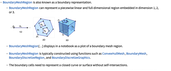
- BoundaryMeshRegionは,境界表現としても知られている.
- BoundaryMeshRegionは,次元1,2あるいは3に埋め込まれた,区分線形および全次元の領域を表すことができる.
- BoundaryMeshRegion[…]は,ノートブック中に境界メッシュ領域のプロットとして表示される.
- BoundaryMeshRegionは,一般に,ConvexHullMesh,BoundaryMesh,BoundaryDiscretizeRegion,BoundaryDiscretizeGraphics等の関数を使って構築される.
- 境界セルは,自己交差のない閉じた曲線あるいは曲面を表さなければならない.
- BoundaryMeshRegion[{p1,p2,…},b1,b2,…]では,境界曲線あるいは境界面の biは,自己交差あるいは互いに交差してはならない.
- BoundaryMeshRegion[{p1,p2,…},b1,b2,…]では,点 p から発する任意の無限の放射線が境界集合 biと奇数回交差しなければ,点 p は境界曲線あるいは境界曲面の biに包み込まれた領域にあると考えられる.
- 境界面には次の特殊ラッパー wiを使うことができる.
-
Labeled[cell,…] ラベルを付けて cell を表示する Style[cell,…] 指定されたスタイルで cell を示す Annotation[cell,name->value] 注釈 name->value を cell と関連させる - BoundaryMeshRegionの各セルには,{d,i}の形の一意的なMeshCellIndexが与えられる.ただし,d は幾何次元,i は指標である.
- BoundaryMeshRegionのセルを選ぶ目的で,次のセル指定を使うことができる.
-
{d,i} 次元 d の指標 i のセル {d,ispec} 次元 d の指標指定 ispec のセル {dspec,…} dspec で与えられる次元のセル h[{i1,…}] 頭部 h,頂点指標 i1, …の明示的なセル {c1,c2,…} 明示的なセル ciのリスト - 指標指定 ispec の可能な形
-
i セルの指標 i {i1,i2,…} 指標 ikのセル All すべてのセル patt パターン patt にマッチする指標を持つセル - 次元指定 dspec の可能な形
-
d 明示的な次元 d All 0から領域の幾何次元までのすべての次元 patt パターン patt にマッチする次元 - BoundaryMeshRegionは,最大次元 n-1のセルを含む.n は埋込み次元である.
- BoundaryMeshRegionは,常に,最適化された表現に変換され,AtomQのような関数におけるパターンマッチの目的では生のものとして扱われる.
- BoundaryMeshRegionには,埋込み次元2ではGraphicsと,埋込み次元3ではGraphics3Dと同じオプションに,以下の追加・変更を加えたものが使える.
-
MeshCellLabel Automatic セルのラベルと置き方 MeshCellShapeFunction Automatic セルの形状関数 MeshCellStyle Automatic セルのスタイル MeshCellHighlight {} ハイライトされたセルのリスト MeshCellMarker 0 セルの整数マーカー PlotTheme $PlotTheme メッシュの全体的なテーマ - PlotThemeの可能な設定には,共通のベーステーマ,フォントの特徴テーマ,サイズの特徴テーマがある.
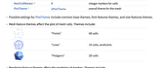
- メッシュの特徴テーマはメッシュセルのプロットに影響する.テーマには次がある.
-

"Points" 0Dセル 
"Lines" 1Dセル,ワイヤーフレーム 
"Polygons" 2Dセル - 描画特徴テーマはメッシュの描画に影響する.テーマには次がある.
-

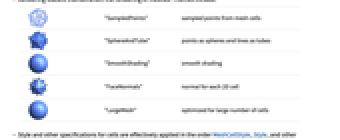
"SampledPoints" メッシュセルからサンプルされた点 
"SphereAndTube" 点を球面として,線を円筒として 
"SmoothShading" 平滑化陰影付け 
"FaceNormals" 各2Dセルについての法線 
"LargeMesh" 多数のセルについて最適化 - セルのスタイルその他の指定は,事実上,MeshCellStyle,Styleその他のラッパーの順に適用される.後の指定は先の指定を無効にする.
- セルラベルのスタイルその他の指定は,事実上,MeshCellLabel,Labeledの順に適用される.後の指定は先の指定を無効にする.
- BoundaryMeshRegionは,RegionMember,RegionDistance,RegionMeasure,NDSolve等の関数で使うことができる.
例題
すべて開く すべて閉じる例 (5)
ℛ = BoundaryMeshRegion[{{0}, {1}}, Point[{1, 2}]]{RegionDimension[ℛ], RegionEmbeddingDimension[ℛ]}{BoundedRegionQ[ℛ], RegionBounds[ℛ]}{RegionMeasure[ℛ], RegionCentroid[ℛ]}RegionMember[ℛ, {1 / 2}]ℛ = BoundaryMeshRegion[{{0, 0}, {1, 0}, {0, 1}}, Line[{1, 2, 3, 1}]]{RegionDimension[ℛ], RegionEmbeddingDimension[ℛ]}{BoundedRegionQ[ℛ], RegionBounds[ℛ]}{RegionMeasure[ℛ], RegionCentroid[ℛ]}RegionMember[ℛ, {1 / 3, 1 / 3}]ℛ = BoundaryMeshRegion[{{0, 0, 0}, {1, 0, 0}, {0, 1, 0}, {0, 0, 1}}, Polygon[{{1, 2, 3}, {1, 2, 4}, {2, 3, 4}, {1, 3, 4}}]]{RegionDimension[ℛ], RegionEmbeddingDimension[ℛ]}{BoundedRegionQ[ℛ], RegionBounds[ℛ]}{RegionMeasure[ℛ], RegionCentroid[ℛ]}RegionMember[ℛ, {1 / 4, 1 / 4, 1 / 4}]ℛ = BoundaryMeshRegion[{{0, 0}, {3, 0}, {3, 3}, {0, 3}, {1, 1}, {2, 1}, {2, 2}, {1, 2}}, Line[{1, 2, 3, 4, 1}], Line[{5, 6, 7, 8, 5}]];HighlightMesh[ℛ, Labeled[0, "Index"]]Area[ℛ]pts = {{0, 0, 0}, {0, 1, 0}, {1, 1, 0}, {1, 0, 0}, {0, 0, 1}, {0, 1, 1}, {1, 1, 1}, {1, 0, 1}};
pts1 = ScalingTransform[{3, 3, 3}][pts];
pts2 = TranslationTransform[{1, 1, 1}][pts];
hex = {{2, 3, 4, 1}, {1, 4, 8, 5}, {4, 3, 7, 8}, {3, 2, 6, 7}, {2, 1, 5, 6}, {5, 8, 7, 6}};ℛ = BoundaryMeshRegion[Join[pts1, pts2], Polygon[hex], Polygon[hex + 8], MeshCellStyle -> Opacity[0.3]];HighlightMesh[ℛ, Labeled[0, "Index"]]Volume[ℛ]スコープ (18)
1D領域 (4)
ℛ = BoundaryMeshRegion[{{0}, {1}}, Point[{1, 2}]]HighlightMeshで点にラベルを付ける:
HighlightMesh[ℛ, Labeled[0, "Index"]]{RegionDimension[ℛ], RegionEmbeddingDimension[ℛ]}{BoundedRegionQ[ℛ], RegionBounds[ℛ]}{RegionMeasure[ℛ], RegionCentroid[ℛ]}RegionMember[ℛ, {0}]BoundaryMeshRegion[{{0}, {3}, {6}, {9}}, {Point[{1, 2}], Point[{3, 4}]}]境界点にStyleを適用する:
BoundaryMeshRegion[{{0}, {1}}, Style[Point[{1, 2}], Red]]BoundaryMeshRegion[{{0}, {1}}, Labeled[Point[{1, 2}], "Index"]]2D領域 (4)
ℛ = BoundaryMeshRegion[{{0, 0}, {3, 0}, {0, 3}}, Line[{1, 2, 3, 1}]]HighlightMeshで線分にラベルを付ける:
HighlightMesh[ℛ, Labeled[1, "Index"]]{RegionDimension[ℛ], RegionEmbeddingDimension[ℛ]}{BoundedRegionQ[ℛ], RegionBounds[ℛ]}{RegionMeasure[ℛ], RegionCentroid[ℛ]}RegionMember[ℛ, {1, 1}]ℛ = BoundaryMeshRegion[{{0, 0}, {3, 0}, {3, 3}, {0, 3}, {1, 1}, {2, 1}, {2, 2}, {1, 2}}, Line[{1, 2, 3, 4, 1}], Line[{5, 6, 7, 8, 5}]];HighlightMeshを使い,点に対応する指標でラベルを付ける:
HighlightMesh[ℛ, Labeled[0, "Index"]]特定の境界線にStyleを適用する:
BoundaryMeshRegion[{{0, 0}, {3, 0}, {3, 3}, {0, 3}, {1, 1}, {2, 1}, {2, 2}, {1, 2}}, Line[{1, 2, 3, 4, 1}], Style[Line[{5, 6, 7, 8, 5}], Red]]BoundaryMeshRegion[{{0, 0}, {3, 0}, {3, 3}, {0, 3}, {1, 1}, {2, 1}, {2, 2}, {1, 2}}, Line[{1, 2, 3, 4, 1}], Labeled[Line[{5, 6, 7, 8, 5}], "Index"]]3D領域 (4)
ℛ = BoundaryMeshRegion[{{0, 0, 0}, {4, 0, 0}, {0, 4, 0}, {0, 0, 4}}, Polygon[{{1, 2, 3}, {1, 2, 4}, {2, 3, 4}, {1, 3, 4}}]]HighlightMeshで線分にラベルを付ける:
HighlightMesh[ℛ, Labeled[1, "Index"]]{RegionDimension[ℛ], RegionEmbeddingDimension[ℛ]}{BoundedRegionQ[ℛ], RegionBounds[ℛ]}{RegionMeasure[ℛ], RegionCentroid[ℛ]}RegionMember[ℛ, {1, 1, 1}]pts = {{0, 0, 0}, {0, 1, 0}, {1, 1, 0}, {1, 0, 0}, {0, 0, 1}, {0, 1, 1}, {1, 1, 1}, {1, 0, 1}};
pts1 = ScalingTransform[{3, 3, 3}][pts];
pts2 = TranslationTransform[{1, 1, 1}][pts];
hex = {{2, 3, 4, 1}, {1, 4, 8, 5}, {4, 3, 7, 8}, {3, 2, 6, 7}, {2, 1, 5, 6}, {5, 8, 7, 6}};ℛ = BoundaryMeshRegion[Join[pts1, pts2], Polygon[hex], Polygon[hex + 8], MeshCellStyle -> Opacity[0.3]];HighlightMesh[ℛ, Labeled[0, "Index"]]特定の境界面にStyleを適用する:
pts = {{1, -1, -3}, {1, -1, 1}, {1, 3, 1}, {-3, -1, 1}};
i = {{1, 2, 3}, {1, 2, 4}, {2, 3, 4}, {1, 3, 4}};BoundaryMeshRegion[Join[pts, pts / 2], Polygon[i + 4], Style[Polygon[i], Opacity[0.5, Red]]]pts = {{1, -1, -3}, {1, -1, 1}, {1, 3, 1}, {-3, -1, 1}};
i = {{1, 2, 3}, {1, 2, 4}, {2, 3, 4}, {1, 3, 4}};BoundaryMeshRegion[Join[pts, pts / 2], Polygon[i + 4], Labeled[Polygon[i], "Index"]]プレゼンテーション (6)
BoundaryMeshRegion[[image], PlotTheme -> "Points"]BoundaryMeshRegion[[image], PlotTheme -> "Lines"]BoundaryMeshRegion[[image], PlotTheme -> "Polygons"]BoundaryMeshRegion[[image], PlotTheme -> "SampledPoints"]BoundaryMeshRegion[[image], PlotTheme -> "SmoothShading"]BoundaryMeshRegion[[image], PlotTheme -> "FaceNormals"]オプション (127)
AlignmentPoint (1)
座標を使って3D Insetの整列位置を指定する:
Table[Graphics[{Inset[BoundaryMeshRegion[{{0, 0}, {1, 0}, {0, 1}}, Line[{1, 2, 3, 1}], ImageSize -> 50, AlignmentPoint -> {a, 0}], {0, 0}]}, ImageSize -> 100, Axes -> True, Ticks -> None], {a, {0, 1 / 2, 1}}]Table[Graphics[{Inset[BoundaryMeshRegion[{{0, 0}, {1, 0}, {0, 1}}, Line[{1, 2, 3, 1}], ImageSize -> 50, AlignmentPoint -> {1 / 2, a}], {0, 0}]}, ImageSize -> 100, Axes -> True, Ticks -> None], {a, {0, 1 / 2, 1}}]AspectRatio (1)
AspectRatioの数値を使う:
Table[BoundaryMeshRegion[{{0, 0}, {2, 0}, {1, Sqrt[3]}}, Line[{1, 2, 3, 1}], AspectRatio -> 1 / k], {k, 1, 3}]Axes (2)
AxesEdge (2)
BoundaryMeshRegion[{{0, 0, 0}, {2, 0, 0}, {2, 2, 0}, {0, 2, 0}, {1, 1, 2}}, Polygon[{{1, 2, 5}, {1, 5, 4}, {2, 3, 5}, {3, 4, 5}, {1, 4, 3, 2}}], Boxed -> True, Axes -> True, AxesEdge -> Automatic]BoundaryMeshRegion[{{0, 0, 0}, {2, 0, 0}, {2, 2, 0}, {0, 2, 0}, {1, 1, 2}}, Polygon[{{1, 2, 5}, {1, 5, 4}, {2, 3, 5}, {3, 4, 5}, {1, 4, 3, 2}}], Boxed -> True, Axes -> True, AxesEdge -> {{1, 1}, None, None}]AxesLabel (2)
AxesOrigin (2)
AxesStyle (2)
BoundaryMeshRegion[{{0, 0}, {2, 0}, {1, Sqrt[3]}}, Line[{1, 2, 3, 1}], Axes -> True, AxesStyle -> Directive[Orange, 12]]BoundaryMeshRegion[{{0, 0}, {2, 0}, {1, Sqrt[3]}}, Line[{1, 2, 3, 1}], Axes -> True, AxesStyle -> {Directive[Dashed, Red], Blue}]Background (1)
BaselinePosition (3)
{x, BoundaryMeshRegion[{{0, 0}, {2, 0}, {1, Sqrt[3]}}, Line[{1, 2, 3, 1}], ImageSize -> 50, BaselinePosition -> Center], y}Scaledを使い,グラフィックスのベースラインを高さの割合として指定する:
Table[{x, BoundaryMeshRegion[{{0, 0}, {2, 0}, {1, Sqrt[3]}}, Line[{1, 2, 3, 1}], ImageSize -> 50, BaselinePosition -> Scaled[b]]}, {b, {0, 0.5, 1}}]{x, BoundaryMeshRegion[{{0, 0}, {2, 0}, {1, Sqrt[3]}}, Line[{1, 2, 3, 1}], ImageSize -> 50, BaselinePosition -> Axis], y}BaseStyle (2)
Boxed (2)
BoundaryMeshRegion[{{0, 0, 0}, {2, 0, 0}, {2, 2, 0}, {0, 2, 0}, {1, 1, 2}}, Polygon[{{1, 2, 5}, {1, 5, 4}, {2, 3, 5}, {3, 4, 5}, {1, 4, 3, 2}}], Boxed -> True]BoundaryMeshRegion[{{0, 0, 0}, {2, 0, 0}, {2, 2, 0}, {0, 2, 0}, {1, 1, 2}}, Polygon[{{1, 2, 5}, {1, 5, 4}, {2, 3, 5}, {3, 4, 5}, {1, 4, 3, 2}}], Boxed -> False]BoxRatios (2)
BoundaryMeshRegion[{{0, 0, 0}, {2, 0, 0}, {2, 2, 0}, {0, 2, 0}, {1, 1, 2}}, Polygon[{{1, 2, 5}, {1, 5, 4}, {2, 3, 5}, {3, 4, 5}, {1, 4, 3, 2}}], Boxed -> True, BoxRatios -> {1, 2, 3}]BoundaryMeshRegion[{{0, 0, 0}, {2, 0, 0}, {2, 2, 0}, {0, 2, 0}, {1, 1, 2}}, Polygon[{{1, 2, 5}, {1, 5, 4}, {2, 3, 5}, {3, 4, 5}, {1, 4, 3, 2}}], Boxed -> True, Axes -> True, BoxRatios -> Automatic]BoxStyle (1)
Epilog (1)
FaceGrids (4)
MeshRegion[{{0, 0, 0}, {2, 0, 0}, {2, 2, 0}, {0, 2, 0}, {1, 1, 2}}, Pyramid[{1, 2, 3, 4, 5}], Axes -> True, Boxed -> True, FaceGrids -> All]BoundaryMeshRegion[{{0, 0, 0}, {2, 0, 0}, {2, 2, 0}, {0, 2, 0}, {1, 1, 2}}, Polygon[{{1, 2, 5}, {1, 5, 4}, {2, 3, 5}, {3, 4, 5}, {1, 4, 3, 2}}], Axes -> True, Boxed -> True, FaceGrids -> {{0, 0, 1}, {0, 0, -1}}]BoundaryMeshRegion[{{0, 0, 0}, {2, 0, 0}, {2, 2, 0}, {0, 2, 0}, {1, 1, 2}}, Polygon[{{1, 2, 5}, {1, 5, 4}, {2, 3, 5}, {3, 4, 5}, {1, 4, 3, 2}}], Axes -> True, Boxed -> True, FaceGrids -> {{0, -1, 0}}]BoundaryMeshRegion[{{0, 0, 0}, {2, 0, 0}, {2, 2, 0}, {0, 2, 0}, {1, 1, 2}}, Polygon[{{1, 2, 5}, {1, 5, 4}, {2, 3, 5}, {3, 4, 5}, {1, 4, 3, 2}}], Axes -> True, Boxed -> True, FaceGrids -> {{{0, -1, 0}, {{1}, {2 / 3, 4 / 3}}}}]FaceGridsStyle (1)
Frame (2)
FrameLabel (2)
BoundaryMeshRegion[{{0, 0}, {2, 0}, {1, Sqrt[3]}}, Line[{1, 2, 3, 1}], Frame -> True, FrameLabel -> {x, y}]BoundaryMeshRegion[{{0, 0}, {2, 0}, {1, Sqrt[3]}}, Line[{1, 2, 3, 1}], Frame -> True, FrameLabel -> {{a, b}, {c, d}}]FrameStyle (2)
BoundaryMeshRegion[{{0, 0}, {2, 0}, {1, Sqrt[3]}}, Line[{1, 2, 3, 1}], Frame -> True, FrameStyle -> Directive[Thick, Gray]]BoundaryMeshRegion[{{0, 0}, {2, 0}, {1, Sqrt[3]}}, Line[{1, 2, 3, 1}], Frame -> True, FrameStyle -> {{Thick, Directive[Thick, Dashed]}, {Blue, Red}}]FrameTicks (3)
BoundaryMeshRegion[{{0, 0}, {2, 0}, {1, Sqrt[3]}}, Line[{1, 2, 3, 1}], Frame -> True, FrameTicks -> None]BoundaryMeshRegion[{{0, 0}, {2, 0}, {1, Sqrt[3]}}, Line[{1, 2, 3, 1}], Frame -> True, FrameTicks -> Automatic]BoundaryMeshRegion[{{0, 0}, {2, 0}, {1, Sqrt[3]}}, Line[{1, 2, 3, 1}], Frame -> True, FrameTicks -> {{None, Automatic}, {Automatic, None}}]FrameTicksStyle (2)
BoundaryMeshRegion[{{0, 0}, {2, 0}, {1, Sqrt[3]}}, Line[{1, 2, 3, 1}], Frame -> True, FrameTicksStyle -> Directive[Orange, 12]]BoundaryMeshRegion[{{0, 0}, {2, 0}, {1, Sqrt[3]}}, Line[{1, 2, 3, 1}], Frame -> True, FrameTicksStyle -> {{Magenta, Blue}, {Red, Green}}]GridLines (3)
BoundaryMeshRegion[{{0, 0}, {2, 0}, {1, Sqrt[3]}}, Line[{1, 2, 3, 1}], GridLines -> Automatic]BoundaryMeshRegion[{{0, 0}, {2, 0}, {1, Sqrt[3]}}, Line[{1, 2, 3, 1}], Axes -> True, GridLines -> {{.5, 1.5}, {.5, 1.5}}]BoundaryMeshRegion[{{-1, 0}, {1, 0}, {0, Sqrt[3]}}, Line[{1, 2, 3, 1}], Axes -> True, GridLines -> {{{-1, Orange}, {-.5, Dotted}, {.5, Dotted}, {1, Orange}}, {0, {.5, Dotted}, {1.5, Dotted}, 2}}]GridLinesStyle (1)
ImageMargins (3)
ImageSizeの外側には余白を入れない:
Framed[BoundaryMeshRegion[{{0, 0}, {2, 0}, {1, Sqrt[3]}}, Line[{1, 2, 3, 1}]]]Framed[BoundaryMeshRegion[{{0, 0}, {2, 0}, {1, Sqrt[3]}}, Line[{1, 2, 3, 1}], ImageMargins -> 20]]Framed[BoundaryMeshRegion[{{0, 0}, {2, 0}, {1, Sqrt[3]}}, Line[{1, 2, 3, 1}], ImageMargins -> {{5, 10}, {20, 30}}]]ImagePadding (4)
BoundaryMeshRegion[{{0, 0}, {2, 0}, {1, Sqrt[3]}}, Line[{1, 2, 3, 1}], ImagePadding -> None, Frame -> True, FrameLabel -> {x, y}]すべてのオブジェクトについて十分な充填を行い,ラベルも残す:
Framed[BoundaryMeshRegion[{{0, 0}, {2, 0}, {1, Sqrt[3]}}, Line[{1, 2, 3, 1}], ImagePadding -> All, Frame -> True, FrameLabel -> {x, y}], FrameMargins -> 0]Framed[BoundaryMeshRegion[{{0, 0}, {2, 0}, {1, Sqrt[3]}}, Line[{1, 2, 3, 1}], ImagePadding -> 40, Frame -> True]]Framed[BoundaryMeshRegion[{{0, 0}, {2, 0}, {1, Sqrt[3]}}, Line[{1, 2, 3, 1}], ImagePadding -> {{40, 10}, {20, 5}}, Frame -> True]]ImageSize (3)
Table[BoundaryMeshRegion[{{0, 0}, {2, 0}, {1, Sqrt[3]}}, Line[{1, 2, 3, 1}], ImageSize -> s], {s, {Tiny, Small}}]{BoundaryMeshRegion[{{0, 0}, {2, 0}, {1, Sqrt[3]}}, Line[{1, 2, 3, 1}], ImageSize -> 100], BoundaryMeshRegion[{{0, 0}, {2, 0}, {1, 3}}, Line[{1, 2, 3, 1}], ImageSize -> 100]}{BoundaryMeshRegion[{{0, 0}, {2, 0}, {1, Sqrt[3]}}, Line[{1, 2, 3, 1}], ImageSize -> {100, 100}], BoundaryMeshRegion[{{0, 0}, {2, 0}, {1, 3}}, Line[{1, 2, 3, 1}], ImageSize -> {100, 100}]}LabelStyle (1)
Lighting (4)
BoundaryMeshRegion[{{0, 0, 0}, {2, 0, 0}, {2, 2, 0}, {0, 2, 0}, {1, 1, 2}}, Polygon[{{1, 2, 5}, {1, 5, 4}, {2, 3, 5}, {3, 4, 5}, {1, 4, 3, 2}}], Lighting -> {{"Ambient", Orange}}]Table[BoundaryMeshRegion[{{0, 0, 0}, {2, 0, 0}, {2, 2, 0}, {0, 2, 0}, {1, 1, 2}}, Polygon[{{1, 2, 5}, {1, 5, 4}, {2, 3, 5}, {3, 4, 5}, {1, 4, 3, 2}}], Lighting -> {{"Directional", c, {{1.5, 0, 2}, {0, 0, 0}}}}], {c, {Red, Yellow, Blue}}]Table[BoundaryMeshRegion[{{0, 0, 0}, {2, 0, 0}, {2, 2, 0}, {0, 2, 0}, {1, 1, 2}}, Polygon[{{1, 2, 5}, {1, 5, 4}, {2, 3, 5}, {3, 4, 5}, {1, 4, 3, 2}}], Lighting -> {{"Point", c, {1.5, 0, 3}}}], {c, {Red, Yellow, Blue}}]Table[BoundaryMeshRegion[{{0, 0, 0}, {2, 0, 0}, {2, 2, 0}, {0, 2, 0}, {1, 1, 2}}, Polygon[{{1, 2, 5}, {1, 5, 4}, {2, 3, 5}, {3, 4, 5}, {1, 4, 3, 2}}], Lighting -> {{"Spot", c, {{1, 1, 2.5}, {1, 1, 2}}, Pi / 8}}], {c, {Red, Yellow, Blue}}]MeshCellHighlight (3)
MeshCellHighlightを使ってBoundaryMeshRegionの一部のハイライトを指定することができる:
BoundaryMeshRegion[{{0, 0}, {1, 0}, {0, 1}}, Line[{1, 2, 3, 1}], MeshCellHighlight -> {{1, All} -> Red, {0, All} -> Green}]面を透過的にすることで,3D BoundaryMeshRegionの内部構造を見ることができる:
BoundaryMeshRegion[{{0, 0, 0}, {1, 0, 0}, {0, 1, 0}, {0, 0, 1}}, Polygon[{{1, 2, 3}, {1, 2, 4}, {2, 3, 4}, {1, 3, 4}}], MeshCellHighlight -> {{2, All} -> Opacity[0.5, Orange]}]BoundaryMeshRegion[{{0, 0}, {1, 0}, {0, 1}}, Line[{1, 2, 3, 1}], MeshCellHighlight -> {{1, 1} -> {Thick, Red}, {1, 2} -> {Dashed, Green}}]MeshRegion[{{0}, {1}, {2}}, Line[{{1, 2, 3}}], MeshCellHighlight -> {{1, 1} -> {Thick, Red}, {1, 2} -> {Dashed, Green}}]BoundaryMeshRegion[{{0, 0}, {1, 0}, {0, 1}}, Line[{1, 2, 3, 1}], MeshCellHighlight -> {Line[{1, 2}] -> {Thick, Red}, Line[{2, 3}] -> {Dashed, Green}}]MeshCellLabel (11)
MeshCellLabelを使ってBoundaryMeshRegionの各部分にラベルを付けることができる:
BoundaryMeshRegion[{{0, 0}, {3, 0}, {3, 3}, {0, 3}, {1, 1}, {2, 1}, {2, 2}, {1, 2}}, Line[{1, 2, 3, 4, 1}], Line[{5, 6, 7, 8, 5}], MeshCellLabel -> {1 -> "Index"}]MeshCellLabelは,"Index","CellIndex"あるいは"Cell"で,セルの指標を明らかにすることができる:
Table[BoundaryMeshRegion[{{0, 0}, {1, 0}, {0, 1}}, Line[{1, 2, 3, 1}], MeshCellLabel -> {{{0, 3}, {1, 2}} -> cl}], {cl, {"Index", "CellIndex", "Cell"}}]BoundaryMeshRegion[{{0, 0}, {6, 0}, {3, 3}, {3, 6}, {0, 3}}, Line[{1, 2, 3, 4, 5, 1}], MeshCellLabel -> {0 -> "Index", {{1, 1}} -> [image], {{1, 2}} -> Sqrt[a^2 + b^2], {1, 3} -> "North", {1, 4} -> [image], {1, 5} -> [image]}]BoundaryMeshRegion[{{0, 0}, {1, 0}, {0, 1}}, Line[{1, 2, 3, 1}], MeshCellLabel -> {All -> Placed["Cell", Tooltip]}]Allを使ってすべてのセルを指定することができる:
BoundaryMeshRegion[{{0, 0}, {1, 0}, {0, 1}}, Line[{1, 2, 3, 1}], MeshCellLabel -> {All -> "x"}]BoundaryMeshRegion[{{0, 0}, {1, 0}, {0, 1}}, Line[{1, 2, 3, 1}], MeshCellLabel -> "x"]BoundaryMeshRegion[{{0, 0}, {1, 0}, {0, 1}}, Line[{1, 2, 3, 1}], MeshCellLabel -> {0 -> "point", 1 -> "line"}]BoundaryMeshRegion[{{0, 0}, {1, 0}, {0, 1}}, Line[{1, 2, 3, 1}], MeshCellLabel -> {{0, {1, 2}} -> "Index", {1, 1} -> "Cell"}]BoundaryMeshRegion[{{0, 0}, {1, 0}, {0, 1}}, Line[{1, 2, 3, 1}], MeshCellLabel -> {Point[{1, 2}] -> "Index", Line[{1, 2}] -> "Cell"}]BoundaryMeshRegion[{{0, 0}, {1, 0}, {0, 1}}, Line[{1, 2, 3, 1}], MeshCellLabel -> {{{0, 1}, {1, 2}} -> "Cell"}]BoundaryMeshRegion[{{0, 0, 0}, {1, 0, 0}, {0, 1, 0}, {0, 0, 1}}, Polygon[{{1, 2, 3}, {1, 2, 4}, {2, 3, 4}, {1, 3, 4}}], MeshCellLabel -> {{0 | 2} -> "CellIndex"}]BoundaryMeshRegion[{{0, 0}, {3, 0}, {3, 3}, {0, 3}, {1, 1}, {2, 1}, {2, 2}, {1, 2}}, Line[{1, 2, 3, 4, 1}], Line[{5, 6, 7, 8, 5}], MeshCellLabel -> {{1, _ ? EvenQ} -> "Index"}]BoundaryMeshRegion[{{0, 0}, {3, 0}, {3, 3}, {0, 3}, {1, 1}, {2, 1}, {2, 2}, {1, 2}}, Labeled[Line[{1, 2, 3, 4, 1}], "x"], Line[{5, 6, 7, 8, 5}], MeshCellLabel -> {1 -> "Index"}]MeshCellMarker (1)
MeshCellMarkerを使ってBoundaryMeshRegionの各部分に値を割り当てることができる:
BoundaryMeshRegion[{{0, 0}, {1, 0}, {0, 1}}, Line[{1, 2, 3, 1}], MeshCellMarker -> {{1, 1} -> 1, {1, 2} -> 2, {1, 3} -> 3}]MeshCellLabelを使ってマーカーを示す:
BoundaryMeshRegion[{{0, 0}, {1, 0}, {0, 1}}, Line[{1, 2, 3, 1}], MeshCellLabel -> {1 -> "Marker"}, MeshCellMarker -> {{1, 1} -> 1, {1, 2} -> 2, {1, 3} -> 3}]MeshCellShapeFunction (2)
MeshCellShapeFunctionを使ってBoundaryMeshRegionの各部分についての関数を指定することができる:
BoundaryMeshRegion[{{0, 0}, {1, 0}, {0, 1}}, Line[{1, 2, 3, 1}], MeshCellShapeFunction -> {1 -> (Arrow[#]&), 0 -> (Disk[#, .05]&)}]BoundaryMeshRegion[{{0, 0}, {1, 0}, {0, 1}}, Line[{1, 2, 3, 1}], MeshCellShapeFunction -> {{0, 1} -> (Disk[#, .1]&), {0, 2} -> (Disk[#, {.1, .05}]&)}]BoundaryMeshRegion[{{0, 0}, {1, 0}, {0, 1}}, Line[{1, 2, 3, 1}], MeshCellShapeFunction -> {Point[1] -> (Disk[#, .1]&), Point[2] -> (Disk[#, {.1, .05}]&)}]MeshCellStyle (8)
Allを使って全セルを指定することができる:
BoundaryMeshRegion[{{0, 0}, {1, 0}, {0, 1}}, Line[{1, 2, 3, 1}], MeshCellStyle -> {All -> Red}]BoundaryMeshRegion[{{0, 0}, {1, 0}, {0, 1}}, Line[{1, 2, 3, 1}], MeshCellStyle -> Red]BoundaryMeshRegion[{{0, 0}, {1, 0}, {0, 1}}, Line[{1, 2, 3, 1}], MeshCellStyle -> {0 -> {PointSize[Large], Green}, 1 -> Red}]BoundaryMeshRegion[{{0, 0}, {1, 0}, {0, 1}}, Line[{1, 2, 3, 1}], MeshCellStyle -> {{0, {1, 2}} -> Directive[PointSize[Large], Green], {1, 1} -> Red}]BoundaryMeshRegion[{{0, 0}, {1, 0}, {0, 1}}, Line[{1, 2, 3, 1}], MeshCellStyle -> {Point[{1, 2}] -> Directive[PointSize[Large], Green], Line[{1, 2}] -> Red}]BoundaryMeshRegion[{{0, 0}, {1, 0}, {0, 1}}, Line[{1, 2, 3, 1}], MeshCellStyle -> {{{0, 1}, {1, 2}} -> Red}]BoundaryMeshRegion[{{0, 0, 0}, {1, 0, 0}, {0, 1, 0}, {0, 0, 1}}, Polygon[{{1, 2, 3}, {1, 2, 4}, {2, 3, 4}, {1, 3, 4}}], MeshCellStyle -> {{0 | 1} -> Red}]BoundaryMeshRegion[{{0, 0}, {3, 0}, {3, 3}, {0, 3}, {1, 1}, {2, 1}, {2, 2}, {1, 2}}, Line[{1, 2, 3, 4, 1}], Line[{5, 6, 7, 8, 5}], MeshCellStyle -> {{1, _ ? EvenQ} -> Red}]ℛ = BoundaryMeshRegion[{{0, 0, 0}, {4, 0, 0}, {0, 4, 0}, {0, 0, 4}}, Polygon[{{1, 2, 3}, {1, 2, 4}, {2, 3, 4}, {1, 3, 4}}], MeshCellStyle -> {0 -> {PointSize[Large], Green}, 1 -> {Dashed, Thick, Red}, 2 -> Opacity[0.7, Brown]}]BoundaryMeshRegion[{{0, 0}, {3, 0}, {3, 3}, {0, 3}, {1, 1}, {2, 1}, {2, 2}, {1, 2}}, Style[Line[{1, 2, 3, 4, 1}], Green], Line[{5, 6, 7, 8, 5}], MeshCellStyle -> {1 -> Red}]PlotLabel (2)
TraditionalForm中のグラフィックスの上にラベルを表示する:
BoundaryMeshRegion[{{0, 0}, {2, 0}, {1, Sqrt[3]}}, Line[{1, 2, 3, 1}], PlotLabel -> x ^ 2 + y ^ 2 == 1]Styleをタイプセット関数と一緒に使って表示されるラベルを変更する:
BoundaryMeshRegion[{{0, 0}, {2, 0}, {1, Sqrt[3]}}, Line[{1, 2, 3, 1}], PlotLabel -> Style[Framed[x ^ 2 + y ^ 2 == 1], 16, Red, Background -> Yellow]]PlotRange (3)
BoundaryMeshRegion[{{0, 0}, {2, 0}, {1, Sqrt[3]}}, Line[{1, 2, 3, 1}], Frame -> True, PlotRange -> All]BoundaryMeshRegion[{{0, 0}, {2, 0}, {1, Sqrt[3]}}, Line[{1, 2, 3, 1}], PlotRange -> {{0, 2}, {0, 1}}, Frame -> True]PlotRangeでの切取りを強制する:
BoundaryMeshRegion[{{0, 0}, {2, 0}, {1, Sqrt[3]}}, Line[{1, 2, 3, 1}], PlotRange -> {{0, 2}, {0, 1}}, PlotRangeClipping -> True, Frame -> True]PlotRange->s はPlotRange->{{-s, s}, {-s, s}}に等しい:
BoundaryMeshRegion[{{-2, -2}, {2, -2}, {0, Sqrt[3]}}, Line[{1, 2, 3, 1}], Frame -> True, PlotRange -> 1]PlotRangeClipping (2)
グラフィックスオブジェクトがPlotRangeの外側に広がることを許す:
BoundaryMeshRegion[{{-2, -2}, {2, -2}, {0, Sqrt[3]}}, Line[{1, 2, 3, 1}], Frame -> True, PlotRange -> 1, PlotRangeClipping -> False]PlotRangeですべてのグラフィックスオブジェクトを切り取る:
BoundaryMeshRegion[{{-2, -2}, {2, -2}, {0, Sqrt[3]}}, Line[{1, 2, 3, 1}], Frame -> True, PlotRange -> 1, PlotRangeClipping -> True]PlotRangePadding (3)
BoundaryMeshRegion[{{0, 0}, {2, 0}, {1, Sqrt[3]}}, Line[{1, 2, 3, 1}], PlotRangePadding -> 1, Frame -> True]Scaled座標を使って充填を含める:
BoundaryMeshRegion[{{0, 0}, {2, 0}, {1, Sqrt[3]}}, Line[{1, 2, 3, 1}], PlotRangePadding -> Scaled[0.1], Frame -> True]BoundaryMeshRegion[{{0, 0}, {2, 0}, {1, Sqrt[3]}}, Line[{1, 2, 3, 1}], PlotRangePadding -> {{0.5, 1}, {0.3, 0.3}}, Frame -> True]PlotRegion (3)
BoundaryMeshRegion[{{0, 0}, {2, 0}, {1, Sqrt[3]}}, Line[{1, 2, 3, 1}], Frame -> True, FrameTicks -> False, Background -> LightBlue]グラフィックスのコンテンツが各方向で領域の内側半分になるように制限する:
BoundaryMeshRegion[{{0, 0}, {2, 0}, {1, Sqrt[3]}}, Line[{1, 2, 3, 1}], Frame -> True, FrameTicks -> False, PlotRegion -> {{0.25, 0.75}, {0.25, 0.75}}, Background -> LightBlue]ImagePaddingはグラフィックスの周囲を充填するためにも使うことができる:
BoundaryMeshRegion[{{0, 0}, {2, 0}, {1, Sqrt[3]}}, Line[{1, 2, 3, 1}], Frame -> True, FrameTicks -> False, ImagePadding -> 30, Background -> LightBlue]PlotTheme (9)
基本テーマ (2)
BoundaryMeshRegion[{{1, -1, -3}, {1, -1, 1}, {1, 3, 1}, {-3, -1, 1}}, Polygon[{{1, 2, 3}, {1, 2, 4}, {2, 3, 4}, {1, 3, 4}}], PlotTheme -> "Detailed"]BoundaryMeshRegion[{{1, -1, -3}, {1, -1, 1}, {1, 3, 1}, {-3, -1, 1}}, Polygon[{{1, 2, 3}, {1, 2, 4}, {2, 3, 4}, {1, 3, 4}}], PlotTheme -> "Monochrome"]特別なテーマ (7)
BoundaryMeshRegion[{{1, -1, -3}, {1, -1, 1}, {1, 3, 1}, {-3, -1, 1}}, Polygon[{{1, 2, 3}, {1, 2, 4}, {2, 3, 4}, {1, 3, 4}}], PlotTheme -> "Points"]BoundaryMeshRegion[{{1, -1, -3}, {1, -1, 1}, {1, 3, 1}, {-3, -1, 1}}, Polygon[{{1, 2, 3}, {1, 2, 4}, {2, 3, 4}, {1, 3, 4}}], PlotTheme -> "Lines"]BoundaryMeshRegion[{{1, -1, -3}, {1, -1, 1}, {1, 3, 1}, {-3, -1, 1}}, Polygon[{{1, 2, 3}, {1, 2, 4}, {2, 3, 4}, {1, 3, 4}}], PlotTheme -> "Polygons"]BoundaryMeshRegion[{{1, -1, -3}, {1, -1, 1}, {1, 3, 1}, {-3, -1, 1}}, Polygon[{{1, 2, 3}, {1, 2, 4}, {2, 3, 4}, {1, 3, 4}}], PlotTheme -> "SampledPoints"]BoundaryMeshRegion[{{1, -1, -3}, {1, -1, 1}, {1, 3, 1}, {-3, -1, 1}}, Polygon[{{1, 2, 3}, {1, 2, 4}, {2, 3, 4}, {1, 3, 4}}], PlotTheme -> "SphereAndTube"]BoundaryMeshRegion[{{1, -1, -3}, {1, -1, 1}, {1, 3, 1}, {-3, -1, 1}}, Polygon[{{1, 2, 3}, {1, 2, 4}, {2, 3, 4}, {1, 3, 4}}], PlotTheme -> "SmoothShading"]BoundaryMeshRegion[{{1, -1, -3}, {1, -1, 1}, {1, 3, 1}, {-3, -1, 1}}, Polygon[{{1, 2, 3}, {1, 2, 4}, {2, 3, 4}, {1, 3, 4}}], PlotTheme -> "FaceNormals"]Prolog (1)
bg = Graphics[Polygon[{{0, 0}, {1, 0}, {1, 1}, {0, 1}}, VertexColors -> {Orange, Orange, White, White}], AspectRatio -> Full];BoundaryMeshRegion[{{0, 0}, {2, 0}, {1, Sqrt[3]}}, Line[{1, 2, 3, 1}], Prolog -> Inset[bg, Scaled[{0, 0}], Scaled[{0, 0}]]]BoundaryMeshRegion[{{0, 0}, {3, 0}, {0, 3}}, Line[{1, 2, 3, 1}], Prolog -> Inset[bg, Scaled[{0, 0}], Scaled[{0, 0}]]]RotateLabel (2)
BoundaryMeshRegion[{{0, 0}, {2, 0}, {1, Sqrt[3]}}, Line[{1, 2, 3, 1}], Frame -> True, FrameLabel -> {None, "y axis"}, RotateLabel -> True]BoundaryMeshRegion[{{0, 0}, {2, 0}, {1, Sqrt[3]}}, Line[{1, 2, 3, 1}], Frame -> True, FrameLabel -> {None, "y axis"}, RotateLabel -> False]SphericalRegion (2)
連続する画像が,方向とは無関係に,同じサイズになるようにする:
Table[BoundaryMeshRegion[{{0, 0, 0}, {2, 0, 0}, {2, 2, 0}, {0, 2, 0}, {1, 1, 2}}, Polygon[{{1, 2, 5}, {1, 5, 4}, {2, 3, 5}, {3, 4, 5}, {1, 4, 3, 2}}], SphericalRegion -> True, ImageSize -> 80, ViewPoint -> 3.{ Sin[t], Cos[t], 1}], {t, 0, 4}]SphericalRegionがないと,各画像は可能な限り大きくされる:
Table[BoundaryMeshRegion[{{0, 0, 0}, {2, 0, 0}, {2, 2, 0}, {0, 2, 0}, {1, 1, 2}}, Polygon[{{1, 2, 5}, {1, 5, 4}, {2, 3, 5}, {3, 4, 5}, {1, 4, 3, 2}}], ImageSize -> 80, ViewPoint -> 3.{ Sin[t], Cos[t], 1}], {t, 0, 4}]Ticks (3)
BoundaryMeshRegion[{{0, 0}, {2, 0}, {1, Sqrt[3]}}, Line[{1, 2, 3, 1}], Axes -> True, Ticks -> None]BoundaryMeshRegion[{{0, 0}, {2, 0}, {1, Sqrt[3]}}, Line[{1, 2, 3, 1}], Axes -> True, Ticks -> Automatic]BoundaryMeshRegion[{{0, 0}, {2, 0}, {1, Sqrt[3]}}, Line[{1, 2, 3, 1}], Ticks -> {{1, 2, 3}, {1, 3}}, Axes -> True]TicksStyle (2)
BoundaryMeshRegion[{{0, 0}, {2, 0}, {1, Sqrt[3]}}, Line[{1, 2, 3, 1}], Axes -> True, TicksStyle -> Directive[Red, Bold]]BoundaryMeshRegion[{{0, 0}, {2, 0}, {1, Sqrt[3]}}, Line[{1, 2, 3, 1}], Axes -> True, TicksStyle -> {Directive[Red, Bold], Directive[Blue, 12]}]ViewAngle (1)
ViewCenter (1)
ViewMatrix (1)
BoundaryMeshRegion[{{0, 0, 0}, {2, 0, 0}, {2, 2, 0}, {0, 2, 0}, {1, 1, 2}}, Polygon[{{1, 2, 5}, {1, 5, 4}, {2, 3, 5}, {3, 4, 5}, {1, 4, 3, 2}}], ViewMatrix -> {TransformationMatrix[RescalingTransform[{{-1, 1}, {-1, 1}, {-1, 1}}]], {{1, 0, 0, 0}, {0, 1, 0, 0}, {0, 0, -1, 0}, {0, 0, 0, 1}}}]ViewPoint (3)
BoundaryMeshRegion[{{0, 0, 0}, {2, 0, 0}, {2, 2, 0}, {0, 2, 0}, {1, 1, 2}}, Polygon[{{1, 2, 5}, {1, 5, 4}, {2, 3, 5}, {3, 4, 5}, {1, 4, 3, 2}}], ViewPoint -> {Pi, Pi / 2, 2}]{BoundaryMeshRegion[{{0, 0, 0}, {2, 0, 0}, {2, 2, 0}, {0, 2, 0}, {1, 1, 2}}, Polygon[{{1, 2, 5}, {1, 5, 4}, {2, 3, 5}, {3, 4, 5}, {1, 4, 3, 2}}], ViewPoint -> Front],
BoundaryMeshRegion[{{0, 0, 0}, {2, 0, 0}, {2, 2, 0}, {0, 2, 0}, {1, 1, 2}}, Polygon[{{1, 2, 5}, {1, 5, 4}, {2, 3, 5}, {3, 4, 5}, {1, 4, 3, 2}}], ViewPoint -> Top]}{BoundaryMeshRegion[{{0, 0, 0}, {2, 0, 0}, {2, 2, 0}, {0, 2, 0}, {1, 1, 2}}, Polygon[{{1, 2, 5}, {1, 5, 4}, {2, 3, 5}, {3, 4, 5}, {1, 4, 3, 2}}], ViewPoint -> {0, -Infinity, 0}],
BoundaryMeshRegion[{{0, 0, 0}, {2, 0, 0}, {2, 2, 0}, {0, 2, 0}, {1, 1, 2}}, Polygon[{{1, 2, 5}, {1, 5, 4}, {2, 3, 5}, {3, 4, 5}, {1, 4, 3, 2}}], ViewPoint -> {0, 0, Infinity}]}ViewRange (2)
デフォルトで,範囲はすべてのオブジェクトを含めるのに十分である:
BoundaryMeshRegion[{{0, 0, 0}, {2, 0, 0}, {2, 2, 0}, {0, 2, 0}, {1, 1, 2}}, Polygon[{{1, 2, 5}, {1, 5, 4}, {2, 3, 5}, {3, 4, 5}, {1, 4, 3, 2}}], ViewPoint -> {1, 0, 1.5}, SphericalRegion -> True]BoundaryMeshRegion[{{0, 0, 0}, {2, 0, 0}, {2, 2, 0}, {0, 2, 0}, {1, 1, 2}}, Polygon[{{1, 2, 5}, {1, 5, 4}, {2, 3, 5}, {3, 4, 5}, {1, 4, 3, 2}}], ViewPoint -> {1, 0, 1.5}, ViewRange -> {3.5, 7.2}, SphericalRegion -> True]ViewVector (1)
ViewVertical (2)
BoundaryMeshRegion[{{0, 0, 0}, {2, 0, 0}, {2, 2, 0}, {0, 2, 0}, {1, 1, 2}}, Polygon[{{1, 2, 5}, {1, 5, 4}, {2, 3, 5}, {3, 4, 5}, {1, 4, 3, 2}}], ViewVertical -> {1, 0, 0}]Table[BoundaryMeshRegion[{{0, 0, 0}, {2, 0, 0}, {2, 2, 0}, {0, 2, 0}, {1, 1, 2}}, Polygon[{{1, 2, 5}, {1, 5, 4}, {2, 3, 5}, {3, 4, 5}, {1, 4, 3, 2}}], ViewVertical -> v], {v, {{1, 0, 1}, {.5, 0, 1}, {0, -.5, 1}, {0, -1, 1}}}]アプリケーション (6)
多角形 (2)
交差しない多角形はBoundaryMeshRegionでもある:
RegularPolygonMesh[n_Integer] :=
BoundaryMeshRegion[Table[{Cos[k 2π / n], Sin[k 2π / n]}, {k, n}], Line[Append[Range[n], 1]]]Table[RegularPolygonMesh[n], {n, 3, 10}]Area /@ %Table[Area[RegularPolygonMesh[n]], {n, {10, 10 ^ 2, 10 ^ 3}}]2Dで,複数の矩形の穴があるBoundaryMeshRegionを作る.次は内部の矩形の座標である:
rectangleCoords[{i_, j_}] := rectangleCoords[{i, j}, {0.5, 0.5}];
rectangleCoords[{i_, j_}, {α_, β_}] := {{i - α / 2, j - β / 2}, {i + α / 2, j - β / 2}, {i + α / 2, j + β / 2}, {i - α / 2, j + β / 2}};rectangleIndexes[i_] := Line[i - 1 + {1, 2, 3, 4, 1}];RectangleHoleMesh[{m_, n_}] :=
Module[{oc, hc},
hc = Flatten[Table[rectangleCoords[{i, j}], {j, n}, {i, m}], 2];
oc = {{0, 0}, {m + 1, 0}, {m + 1, n + 1}, {0, n + 1}};
BoundaryMeshRegion[Join[hc, oc],
rectangleIndexes[4 m n + 1],
Sequence@@Table[rectangleIndexes[i], {i, 1, 4 m n, 4}]
]
]RectangleHoleMesh[{20, 10}]RegionMeasure[%]多面体 (4)
交差しない多面体はBoundaryMeshRegionでもある:
PolyhedronMesh[name_String] :=
BoundaryMeshRegion[PolyhedronData[name, "Vertices"], Polygon[PolyhedronData[name, "FaceIndices"]]]PolyhedronMesh /@ PolyhedronData["Archimedean"]ColoredPolyhedron[name_String] :=
Module[{faces},
faces = GatherBy[PolyhedronData[name, "FaceIndices"], Length[#]&];
BoundaryMeshRegion[PolyhedronData[name, "Vertices"], Table[Style[Polygon[faces[[i]]], ColorData[100, i]], {i, Length[faces]}]]
]Magnify[ColoredPolyhedron /@ PolyhedronData["Archimedean"], 0.5]複数の内部直方体の境界を使い,複数の空洞があるBoundaryMeshRegionを作る.以下は内部直方体の座標である:
cuboidCoords[{i_, j_, k_}] := cuboidCoords[{i, j, k}, {0.5, 0.5, 0.5}];
cuboidCoords[{i_, j_, k_}, {α_, β_, γ_}] :=
{{i - α / 2, j - β / 2, k - γ / 2}, {i - α / 2, j + β / 2, k - γ / 2}, {i + α / 2, j + β / 2, k - γ / 2}, {i + α / 2, j - β / 2, k - γ / 2}, {i - α / 2, j - β / 2, k + γ / 2}, {i - α / 2, j + β / 2, k + γ / 2}, {i + α / 2, j + β / 2, k + γ / 2}, {i + α / 2, j - β / 2, k + γ / 2}};cuboidIndexes[i_] := Polygon[(i - 1) + {{2, 3, 4, 1}, {1, 4, 8, 5}, {4, 3, 7, 8}, {3, 2, 6, 7}, {2, 1, 5, 6}, {5, 8, 7, 6}}]CuboidVoidMesh[{m_, n_, p_}] :=
Module[{oc, vc},
vc = Flatten[Table[cuboidCoords[{i, j, k}], {k, p}, {j, n}, {i, m}], 3];
oc = {{0, 0, 0}, {0, n + 1, 0}, {m + 1, n + 1, 0}, {m + 1, 0, 0}, {0, 0, p + 1}, {0, n + 1, p + 1}, {m + 1, n + 1, p + 1}, {m + 1, 0, p + 1}};
BoundaryMeshRegion[Join[vc, oc],
cuboidIndexes[8 m n p + 1],
Sequence@@Table[cuboidIndexes[i], {i, 1, 8 m n p, 8}]]
]HighlightMesh[CuboidVoidMesh[{5, 4, 3}], Style[2, Opacity[0.3]]]RegionMeasure[%]中に長方形のトンネルが通った直方体の境界メッシュを作る.これは,区間がある2D境界メッシュの積として作ることができる.2D境界メッシュのために上記で使った穴のある多角形と同じ構造を使う:
rectangleCoords[{i_, j_}] := rectangleCoords[{i, j}, {0.5, 0.5}];
rectangleCoords[{i_, j_}, {α_, β_}] := {{i - α / 2, j - β / 2}, {i + α / 2, j - β / 2}, {i + α / 2, j + β / 2}, {i - α / 2, j + β / 2}};rectangleIndexes[i_] := Line[i - 1 + {1, 2, 3, 4, 1}];RectangleHoleMesh[{m_, n_}] :=
Module[{oc, hc},
hc = Flatten[Table[rectangleCoords[{i, j}], {j, n}, {i, m}], 2];
oc = {{0, 0}, {m + 1, 0}, {m + 1, n + 1}, {0, n + 1}};
BoundaryMeshRegion[Join[hc, oc],
rectangleIndexes[4 m n + 1],
Sequence@@Table[rectangleIndexes[i], {i, 1, 4 m n, 4}]
]
]RectangleHoleMesh[{4, 3}]TunnelMesh[{m_, n_}] :=
BoundaryMesh[RegionProduct[TriangulateMesh[RectangleHoleMesh[{m, n}], MeshQualityGoal -> "Minimal"], MeshRegion[{{0}, {1}}, Line[{1, 2}]]]]TunnelMesh[{4, 3}]HighlightMesh[%, {Style[1, None], Style[2, Opacity[0.5]]}]NIntegrate[1, {x, y, z}∈%]特性と関係 (8)
BoundaryMeshRegionは,全次元の領域を表すことができる:
ℛ = BoundaryMeshRegion[{{0, 0}, {1, 0}, {0, 1}}, Line[{1, 2, 3, 1}]]{RegionEmbeddingDimension[ℛ], RegionDimension[ℛ]}BoundaryMeshRegionは常に有界である:
ℛ = BoundaryMeshRegion[{{0, 0}, {1, 0}, {0, 1}}, Line[{1, 2, 3, 1}]]BoundedRegionQを使って検証し,RegionBoundsを使って実際の境界を調べる:
{BoundedRegionQ[ℛ], RegionBounds[ℛ]}BoundaryMeshRegionQを使って領域がBoundaryMeshRegionかどうかを調べることができる:
ℛ = BoundaryMeshRegion[{{0, 0}, {1, 0}, {0, 1}}, Line[{1, 2, 3, 1}]]BoundaryMeshRegionQ[ℛ]ConvexHullMeshを使って点の集合からBoundaryMeshRegionを作る:
p2 = RandomReal[1, {100, 2}];
p3 = RandomReal[1, {100, 3}];ConvexHullMesh /@ {p2, p3}BoundaryMeshを使ってMeshRegionをBoundaryMeshRegionに変換する:

mr = MeshRegion[{{0, 0}, {1, 0}, {0, 1}, {1, 1}, {2, 0}}, {Triangle[{1, 2, 3}], Triangle[{4, 3, 2}], Line[{4, 5}]}]BoundaryMesh[mr]
BoundaryDiscretizeRegionを使って任意の領域をBoundaryMeshRegionに変換する:

BoundaryDiscretizeRegion[ImplicitRegion[x ^ 2 + y ^ 2 ≤ 1 || y == 0, {x, y}]]より低次元の成分を含めたければ’DiscretizeRegionを使うとよい:
DiscretizeRegion[ImplicitRegion[x ^ 2 + y ^ 2 ≤ 1 || y == 0, {x, y}], {{-2, 2}, {-1, 1}}]Showを使って任意のBoundaryMeshRegionをGraphicsに変換する:
ℛ = BoundaryMeshRegion[{{0, 0}, {1, 0}, {0, 1}}, Line[{1, 2, 3, 1}]]Show[ℛ]//InputFormBoundaryMeshRegionは,多くの場合はMeshRegionよりメモリ効率がよい:
pts = RandomReal[{-1, 1}, {50, 2}];{DelaunayMesh[pts], ConvexHullMesh[pts]}ByteCount /@ %関連するガイド
-
▪
- メッシュベースの幾何学的領域 ▪
- 幾何学的計算 ▪
- 偏微分方程式 ▪
- 多面体 ▪
- 3Dプリント
関連するワークフロー
- 3Dプリントを作成する
テキスト
Wolfram Research (2014), BoundaryMeshRegion, Wolfram言語関数, https://reference.wolfram.com/language/ref/BoundaryMeshRegion.html (2015年に更新).
CMS
Wolfram Language. 2014. "BoundaryMeshRegion." Wolfram Language & System Documentation Center. Wolfram Research. Last Modified 2015. https://reference.wolfram.com/language/ref/BoundaryMeshRegion.html.
APA
Wolfram Language. (2014). BoundaryMeshRegion. Wolfram Language & System Documentation Center. Retrieved from https://reference.wolfram.com/language/ref/BoundaryMeshRegion.html
BibTeX
@misc{reference.wolfram_2026_boundarymeshregion, author="Wolfram Research", title="{BoundaryMeshRegion}", year="2015", howpublished="\url{https://reference.wolfram.com/language/ref/BoundaryMeshRegion.html}", note=[Accessed: 08-August-2026]}
BibLaTeX
@online{reference.wolfram_2026_boundarymeshregion, organization={Wolfram Research}, title={BoundaryMeshRegion}, year={2015}, url={https://reference.wolfram.com/language/ref/BoundaryMeshRegion.html}, note=[Accessed: 08-August-2026]}